
Related Manuals for Allora Positive Contact PCS-250

Summary of Contents for Allora Positive Contact PCS-250
- Page 1 PCS-250 SYSTEM PCS-250 SYSTEM INSTALLATION INSTALLATION INSTRUCTIONS INSTRUCTIONS POWER 24VDC TEACH FAULT TIME START FAULT OUTPUT OUTPUT 115V 24V Made in the...
- Page 2 Page 1 PCS-250 SPECIFICATIONS 55.00 mm 45.00 mm SCU100 24VDC Power Supply TCU-250 Control Unit POWER 24VDC OUTPUT 24VDC 0.6A Input Power: 110-240VAC Operating Voltage: 24VDC Input: 24VDC, 250mA TEACH FAULT Output Voltage: 24VDC Maxium Current: 250mA 75.00 mm 74.97 mm DC ON TIME Relay Outputs:...
- Page 3 Page 2 CW Swing direction Before you start The PCS-250 Sensor is a self teaching device. It has the capability of swinging Clockwise (CW) or counterclockwise (CCW) up to 300º. The CW or CCW selection is made on the TCU via a dip switch.
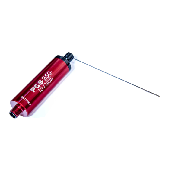
- Page 4 Page 3 Mounting the bracket and sensor Mount the fabricated bracket and attach the clamping ring. Slide the sensor into the clamping ring but do not tighten in to place. Slip on the swing arm assembly ( you do not need to secure it ) and move the sensor forward or backward until the sensing needle is positioned approximately 1.60 mm back from the tip of the tool as shown in FIG 4.
- Page 5 Page 4 TCU Terminal Descriptions Terminals 1 & 2: The TCU operates with 24VDC, note that terminal 1 is + and terminal 2 is - . This unit requires a minimum supply of 250 mA. When powering the TCU with an existing 24VDC power supply, confirm that the supply is capable of additional output capacity to power the TCU.
-
Page 6: Fault Led
Sensor Control Unit Switches Page 5 Please Note: Unless otherwise specified when ordered, the TCU-250 Control Unit has been preset with a CW direction, #2 Time Setting and a HI Rate. OK LED ( See Relay Control Switches Below) The OK LED will illuminate at power on. When a start signal is initiated the LED will momentarily turn off. - Page 7 Page 6 TCU Installation Guide ESD/EMF PROTECTION: The TCU is a microprocessor based unit. When mounting the TCU in the machines electrical cabinet avoid placing it near sources which might produce ESD (electro static discharge), or EMF ( electro magnetic frequencies ), such as large motor starters or high current devices.
- Page 8 Page 7 PCS-250 System Trouble Shooting Guide Please refer to the section that best describes the problem you are having. Determine if you can answer YES to all of the questions. If not, attempt to correct the condition. If at anytime you have questions, please contact our service department at 1-855-TOOL-911 (855-866-5911).
- Page 9 NO POWER TO TCU-250 (No lights illuminated when TCU-250 is powered up and no power to PCS-250.) • If 115VAC, is the power supply supplied by Allora being used? • Is there a clean 24VDC being supplied to the power terminals on the TCU-250? •...
- Page 12 All Positive Contact foam packaging is free of CFC’s, HCFC’s or HFC’s. The foam and its ash is non-toxic, landfill safe and recyclable. Allora International, LLC 1825 Dolphin Drive Unit B Waukesha, WI 53186 Phone +1.262.246.6800 Fax +1.262.246.6866 Website www.alloraintl.com E-Mail info@alloraintl.com...
Need help?
Do you have a question about the Positive Contact PCS-250 and is the answer not in the manual?
Questions and answers