Advertisement
Quick Links
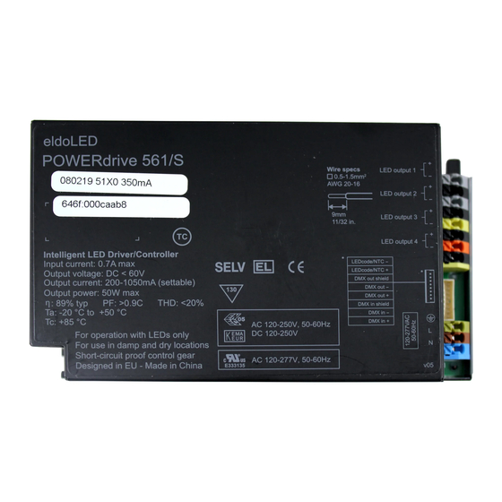
Wiring diagram POWERdrive 561/S, 561/A
Pay attention when connecting the LED groups:
polarity reversal results in no light output and often damages the LEDs
LED output 1
LED output 2
LED output 3
LED output 4
WARNING: Risk of electrical shock. May result in serious injury or death. Disconnect power before servicing or installing.
CAUTION: The device may only be connected and installed by a qualified electrician. All applicable regulations, legislation and build-
ing codes must be observed. Incorrect installation of the device can cause irreparable damage to the device and the connected LEDs.
LED outputs
R(ed) represents channel 1, G(reen) represents channel 2, B(lue) rep-
resents channel 3, and W(hite) represents channel 4. The default
group colour allocation can be changed using the TOOLbox pro and
freely available FluxTool application.
Maximum wiring distance at full load (from LED driver to LED load):
20
AWG value
Distance (m)
14
Distance (ft)
46
Please observe voltage drop over long cable lengths.
Longer cable lengths increase EMI susceptibility.
For POWERdrive 561/A it is recommended to use shielded
multi-core wires between LED driver and LED engine. Prop-
erly connect shield to ground on both sides.
LEDcode/NTC
The LEDcode/NTC interface allows connection of a 47kΩ NTC therm-
istor for closed loop thermal control. The NTC throttle temperature is
programmable through the freely available FluxTool software (see
"Configuring your driver over DMX in").
DMX in/DMX out
Connect the network cable's DMX+, DMX- and DMX shielding wires
to the corresponding pin or wire on the LED driver.
For LED drivers that feature the WH0081S1 wiring harness, the wire
colors on the harness and corresponding colors in a CAT 5 cable are
listed in the following table.
120-277 VAC
19
18
17
16
18
22
28
36
59
72
92
118
©
2015 eldoLED. All rights reserved. v1.3
More documentation and eldoLED's terms and conditions are available at www.eldoled.com.
(PW0561S1, PW0561A1)
1
2
Solid or stranded copper wires only.
-
LEDcode/NTC
+
shield
DMX out
-
+
shield
DMX in
-
+
Wiring harness
DMX out shield
DMX out -
DMX out +
DMX in shield
DMX in -
DMX in +
The WH0081S1 wiring harness can be ordered from eldoLED.
Alternatively, if you wish to use a proprietary solution, the following
molex parts should be used: 1x wire-to-board housing 87439-0800
and 8x crimp terminal 87421-0000.
Configuring your driver over DMX in
Download the FluxTool software from your eldoLED driver's product
web page and connect a TOOLbox pro to DMX in to configure your
driver. You can configure:
• various DMX parameters
• dimming curve
• minimum dimming level
• NTC throttle temperature
• LED drive current per output, from 200mA-1,050mA in 1mA steps
120-277V AC
The driver has been designed for use with universal mains voltage in-
put (120-277V AC, 50/60Hz), and for use with DC input (120-250V, as
used in emergency lighting).
AWG 20-16
2
0.5-1.5 mm
9 mm
0.35 inch
CAT5 cable
black
brown
black/blue
orange
black/white
orange/white
black
brown
blue
orange
white
orange/white
Advertisement

Related Manuals for eldoLED POWERdrive 561/S

Summary of Contents for eldoLED POWERdrive 561/S
- Page 1 For LED drivers that feature the WH0081S1 wiring harness, the wire colors on the harness and corresponding colors in a CAT 5 cable are listed in the following table. © 2015 eldoLED. All rights reserved. v1.3 More documentation and eldoLED’s terms and conditions are available at www.eldoled.com.
- Page 2 Wiring diagram POWERdrive 561/S, 561/A (PW0561S1, PW0561A1) Connecting 3 LED groups Connecting 2 LED groups Connecting 1 LED group eldoLED B.V. Science Park Eindhoven 5125 5692 ED Son The Netherlands T +31 40 7820400 info@eldoled.com eldoLED America One Lithonia Way...
Need help?
Do you have a question about the POWERdrive 561/S and is the answer not in the manual?
Questions and answers