Table of Contents
Advertisement
Quick Links
Installation and Maintenance
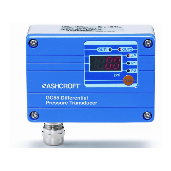
Instructions for GC55
Differential Pressure
Transducer
© 2011 Ashcroft Inc. 250 East Main Street, Stratford, CT 06614 USA
Tel: 203-378-8281, Fax: 203-385-0402 www.ashcroft.com
All sales subject to standard terms and conditions of sale.
I&M011-10158. Rev. C 5/11
Version 1.0 5/11
Advertisement
Table of Contents

Related Manuals for Ashcroft GC55


Summary of Contents for Ashcroft GC55
- Page 1 Instructions for GC55 Differential Pressure Transducer Version 1.0 5/11 © 2011 Ashcroft Inc. 250 East Main Street, Stratford, CT 06614 USA Tel: 203-378-8281, Fax: 203-385-0402 www.ashcroft.com All sales subject to standard terms and conditions of sale. I&M011-10158. Rev. C 5/11...
- Page 3 A failure resulting in injury or damage may be caused by excessive overpressure, excessive vibration or pressure pulsation, excessive instrument temperature, corrosion of the pressure containing parts, or other misuse. Consult Ashcroft Inc., Stratford, Connecticut, USA before installing if there are any questions or concerns. 2. OVERPRESSURE:...
-
Page 5: Table Of Contents
ConTenTs 1. specifications ..........2. Dimension Drawings ........3. Installation ............4. Wiring ..............5. noise Prevention..........6. storage .............. 7. Maintenance ............ 8. Menu navigation ..........9. Function setting Mode ........10. switch setting Mode........11. switch operation..........12. Loop Check Mode ..........13. -
Page 6: Specifications
1. specifications Pressure Range: 75, 100, 150, 250, 300 psid (as noted on the unit) Proof Pressure: 2X F.S. Differential Pressure range (∆P): ∆P=P1(H)-P2(L); as marked on unit Display Range: Diff. pressure range of –5 to 105%F.S. or display of –1999 to 1999 Power supply: •... -
Page 7: Dimension Drawings
operating humidity range: 10 to 85%(with no condensation) storage Temperature: –20 to 60°C (–4 to 140°F) (non freezing) Case construction: IP65/NEMA 4 Pressure Connections ⁄ NPT Female (2) places enclosure Material: Aluminum Weight: 18 ounces *Option selected at time of order. 2. -
Page 8: Installation
IP64 environmental rating. • Pressure Port Connections: ⁄ NPT female, 1 ⁄ turns past hand tight. • Mounting: Remove the GC55 cover, 4 screws, and attach via through holes, (2) places, 0.20˝ diameter. -
Page 9: Wiring
If noise is present in the power supply / wires the pressure display can fluc- tuate and provide incorrect output. Care should be taken to keep the GC55 power supply wires from high voltage lines and use a power line with a high noise rejection ratio. - Page 10 Illustration (1) Illustration (2)
-
Page 11: Menu Navigation
8. Menu navigation (cont.) External Panel and Functions (SEL key can be operated externally) Illustration (3) 8. Menu navigation (cont.) Internal Panel and Functions (cover removed) Illustration (4) -
Page 12: Function Setting Mode
8. Menu navigation (cont.) Pressing the key for 3 seconds displays “---”. To return to MODE measurement mode from each setting mode, the “---” display will flash when 3 seconds have passed. *Note: Zero Adjustment, select P1 and P2 respectively and then use Zero Adjustment, will not function in DP mode. - Page 14 150.0 ¡ 1.000 Filter section The GC55 is equipped with 5 internal time constant filters. Use this function when pressure fluctuations can result in erratic, difficult to read displays. The time constant for the selected filters reflects on the switch outputs as well as the analog output.
-
Page 15: Switch Setting Mode
Entering the setting value in function setting mode resets all of the setting - - - - - No filter - - - - - Time constant 25ms - - - - - Time constant 250ms - - - - - Time constant 2.5 sec - - - - - Time constant 5 sec... - Page 16 independently to a max on/off delay of 2 seconds. In the following explana- tion, if the switch’s output conditions are met their output state will become On, and “Switch LED (OUT1, OUT2)” will light up. PLEASE NOTE that if the switch’s setting value is set outside the display range, the switch’s setting value can be rewritten automati- cally by the function setting mode operation.
-
Page 17: Switch Operation
11. switch operation – Hysteresis/Deadband setting the upper limit. This is the mode in which the switch operates with the setting value (A) as the upper limit. The upper limit setting is determined when you select a positive number (including 0) for setting value (b). setting the lower limit. -
Page 18: Loop Check Mode
operation of Window Comparator 12. Loop Check Mode setup steps In measurement mode press the + LM keys (release within MODE 3 sec.) to change to Loop Check Mode. Regardless of applied pressure, display and analog output can be tested manually using the LM keys, useful for simulation testing of the analog output and switch output wiring. -
Page 19: Other Functions
13. other Functions Basic Key operations In all setting modes, values are set with the LM keys. Use the L key to increase and the M key to decrease the value. A repeat state occurs in three phases of speed when the LM keys are pressed for more than 0.5 seconds to increase or decrease numerical value. - Page 20 1 second when ∆P zero adjustment cannot be done. Maximum / Minimum Pressure Capture The GC55 unit keeps the maximum and minimum pressure level applied to the pressure port as peak and bottom values respectively, in the inter- nal memory.
- Page 21 error Display An error message and a pressure are alternately displayed when one of the following errors occurs while in measurement mode. error Display Definition Definition Pressure above 105% F.S. of sensor range is applied, or when indicated value exceed- ed 1999.
-
Page 22: Maintenance & Warranty
14. MAInTenAnCe AnD WARRAnTY Periodic Inspection Depending upon the type of use periodic inspection is recommeded at least once a year. Please refer to the following items for periodic inspection. (1) Appearance (2) Display/output check via appropriate pressure standard (3) Display/output check via Loop Check CAUTIon •... - Page 24 © 2011 Ashcroft Inc. 250 East Main Street, Stratford, CT 06614 USA Tel: 203-378-8281, Fax: 203-385-0402 www.ashcroft.com All sales subject to standard terms and conditions of sale. I&M011-10158. Rev. C 5/11...
Need help?
Do you have a question about the GC55 and is the answer not in the manual?
Questions and answers