Table of Contents
Advertisement
Quick Links
Advertisement
Table of Contents

Related Manuals for Texas Instruments SWRU197E


Summary of Contents for Texas Instruments SWRU197E
- Page 1 CC Debugger User’s Guide SWRU197E...
-
Page 2: Table Of Contents
Table of Contents Introduction ..........................3 Abbreviations and Acronyms ....................3 Box Contents ..........................4 Operating Conditions of the CC Debugger ................4 Initial Steps ..........................5 Installing the USB driver ......................5 Supported PC Tools ........................5 Connecting the CC Debugger to the Device ................6 Target Connector Details ...................... -
Page 3: Introduction
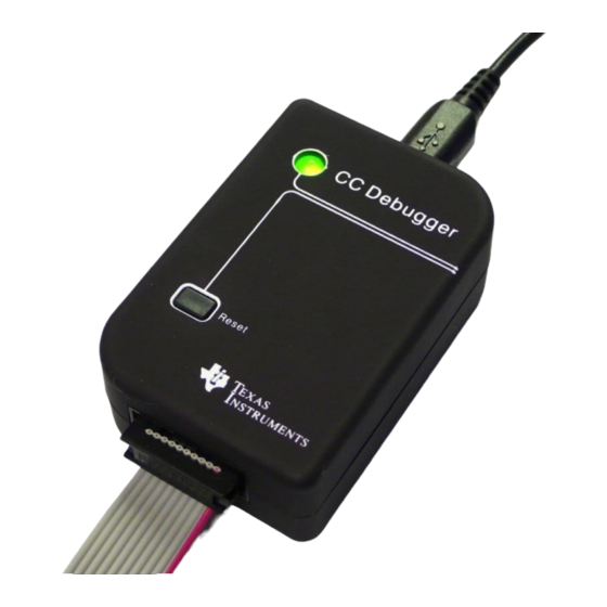
The CC Debugger is primarily used for debugging and programming the flash on CCxxxx 8051-based System-on-Chip (SoC) devices from Texas Instruments. The PC tools available for these purposes are the SmartRF™ Flash Programmer from Texas Instruments and IAR Embedded Workbench® for 8051 from IAR Systems. -
Page 4: Box Contents
Box Contents 1 CC Debugger 1 USB-A to Mini-B USB cable 1 10-pin flat cable with 2x5 2.54 mm connector 1 10-pin flat cable with 2x5 1.27 mm connector 1 Converter board 2.54mm – 1.27 mm connector ... -
Page 5: Initial Steps
Initial Steps Installing the USB driver To get the required USB driver for the CC Debugger, it is necessary to install one of the tools listed below: SmartRF Studio www.ti.com/tool/smartrftm-studio SmartRF Flash Programmer www.ti.com/tool/flash-programmer PurePath Wireless Configurator http://www.ti.com/tool/purepath-wl-cfg... -
Page 6: Connecting The Cc Debugger To The Device
Connecting the CC Debugger to the Device Target Connector Details The target connector, located on the lateral side of the debugger, is a 10-pin 2x5 2.54 mm pitch connector with a direction coded plastic guide. A suggested matching (male) surface mounted connector would be BB02-HP from GradConn. - Page 7 Target Voltage Sense DC (Debug Clock) DD (Debug Data) CSn (SPI Chip Select) SCLK (SPI Clock) RESETn MOSI (SPI Data Out) 3.3V (from debugger) MISO (SPI Data In) Figure 5 - Target Connector Pin-out Please note the concept with the target voltage sense signal. This signal is used by the level converters on the CC Debugger to handle different voltage levels on the target board and the debugger.
-
Page 8: Connecting The Cc Debugger To A System On Chip
Connecting the CC Debugger to a System on Chip 6.2.1 Minimum connection for debugging For successful debugging of a TI 8051-based RF System on Chip, connect the two debug signals Debug Data (DD) and Debug Clock (DC) and the reset signal RESETn to the device. In addition, the CC Debugger must be connected to GND and Vdd on the board. -
Page 9: Minimum Connection For Smartrf Packet Sniffer
6.2.3 Minimum connection for SmartRF Packet Sniffer In order to use the packet sniffer capabilities of the CC Debugger, it is also necessary to connect the SPI bus to the SoC. The SPI interface is used by the CC Debugger for reading the captured RF packets from the SoC. -
Page 10: Connecting The Cc Debugger To A Transceiver
Connecting the CC Debugger to a Transceiver The SPI interface on the CC Debugger can be used to interface many of the CCxxxx transceivers and control them from SmartRF Studio. The transceivers/transmitters/receivers currently supported are: CC1120 CC1121 ... - Page 11 CC Debugger CC112x Connector CC1175 GPIO0 GPIO2 SCLK SCLK 3.3V from debugger. Can RESETn MOSI optionally be used to power the target board MISO RESETn Figure 8 - CC Debugger connected to CC112x/CC1175 CC Debugger CC110L Connector CC113L CC115L...
-
Page 12: Connecting The Cc Debugger To A Cc85Xx
Connecting the CC Debugger to a CC85xx In order to configure the CC85xx devices (i.e. program the flash on the device) with PurePath Wireless Configurator, the device’s SPI interface must be connected to the CC Debugger as shown in the figure below. -
Page 13: Using The Cc Debugger
Using the CC Debugger After having connected the debugger to the target device, the debugger can be powered up by plugging in the USB cable. The debugger will immediately start a device detection process, looking for all known devices. If no devices are detected, the LED will be RED. -
Page 14: Updating The Firmware
Updating the Firmware In order to make sure the CC Debugger works seamlessly with your device, it is important that it has the latest and greatest firmware. This chapter will describe how you can upgrade the firmware automatically from SmartRF Studio or manually from SmartRF Flash Programmer. The chapter will also describe how to resurrect a seemingly broken debugger. - Page 15 Figure 12 - Auto FW upgrade 4. Click "Yes" and let SmartRF Studio do the rest. Figure 13 - Auto FW upgrade 5. Click "Done" and you're good to go. The device should appear in the list of connected devices, now showing the new firmware revision.
-
Page 16: Updating The Firmware Manually In Smartrf Flash Programmer
The debugger will appear in the list of connected devices. Chip type will be listed as N/A. 3. Select the flash image you want to program on the debugger. Normally, you would select: C:\Program Files (x86)\Texas Instruments\SmartRF Tools\Firmware\CC Debugger\cebal_fw_srf05dbg.hex 4. Select the action “Erase, program and verify”... -
Page 17: Forced Boot Recovery Mode
Forced boot recovery mode If, for some reason, the firmware update fails and the CC Debugger appears to be non responsive, there is a way to force the board to only run the bootloader and stop all further execution. In this mode, no attempts will be made to start the firmware, and the board will only allow the user to perform a new firmware upgrade over USB. - Page 18 SmartRF05EB, connect a 10-pin flat cable from the “Ext SoC Debug” plug (P3) on the EB to the “USB Debug” plug (P2) on the CC Debugger. The dead debugger needs power, so connect the USB cable. Turn on the SmartRF05EB or debugger - it should detect the USB Controller (CC2511) on the debugger.
- Page 19 1. After starting the application, first select “Program Evaluation Board” in the “What do you want to program?” drop down box, then select the “EB Bootloader” tab. 2. In the upper left corner, select device: Use SmartRF05EB regardless of the device being used to program the debugger.
-
Page 20: Troubleshooting
Yes – but make sure you have an up to date version of IAR with the new debug driver plug-in from Texas Instruments. You will need version 7.51A or higher. Can the debugger be used as an interface to the RF device for packet sniffing? Yes, this is supported for selected devices. -
Page 21: Schematics
Cebal – CCxxxx Development Tools USB Driver for Windows x86 and x64 www.ti.com/lit/zip/swrc212 DN304 – CCxxxx Development Tools USB Driver Installation Guide www.ti.com/lit/swra366 Texas Instruments Support support.ti.com Texas Instruments Low Power RF Online Community www.ti.com/lprf-forum SmartRF Studio www.ti.com/tool/smartrftm-studio SmartRF Flash Programmer www.ti.com/tool/flash-programmer SmartRF Packet Sniffer www.ti.com/tool/packet-sniffer... -
Page 22: Document History
12 Document History Revision Date Description/Changes 2012-03-01 Corrected typo in chapter 6.2.1. Special debug pin-out for CC2544, not CC2543. Added information about connections for programming of CC85xx devices. Updated info about connections for supported transceivers. Updated driver installation 2012-02-22 information and added more details about firmware upgrade. - Page 24 IMPORTANT NOTICE Texas Instruments Incorporated and its subsidiaries (TI) reserve the right to make corrections, modifications, enhancements, improvements, and other changes to its products and services at any time and to discontinue any product or service without notice. Customers should obtain the latest relevant information before placing orders and should verify that such information is current and complete.
Need help?
Do you have a question about the SWRU197E and is the answer not in the manual?
Questions and answers