
Subscribe to Our Youtube Channel
Summary of Contents for DeLaval MPCII
- Page 1 MEMO – Internal use DeLaval milking point controller MPCII - 0605 - 2006-07-20 94381001.pdf...
-
Page 3: Table Of Contents
Gate valves....................10 Gate switches .................... 11 MPCII with MM15 and Basic functions ............12 MPCII with MM15 and Gate valve and Gate button ........13 MPCII with MM15 and Gate valve or Gate switch ........14 MPCII with FI2 ................... 15 MPCII with MM25 or FI5 ................ - Page 4 Gate valves....................40 Gate switches .................... 41 MPCII with MM15 and Basic functions ............42 MPCII with MM15 and Gate valve and Gate button ........43 MPCII with MM15 and Gate valve or Gate switch ........44 MPCII with FI2 ................... 46 2006-07-20 94381001.pdf...
- Page 5 MPCII with MM25 or FI5 ................47 MPCII addresses ..................... 48 DeLaval milking point controller MPCII....................49 Operation..........................49 Mode description...................... 49 Display ........................50 Key pads ........................50 Numerical key pad ....................52 F key......................52 Numeral keys..................... 52 Enter key ....................
- Page 6 F32 – Today's and yesterday's milk yields read/write function ....64 F39 – Expected milk yield read only ............64 F43 – Show last transponder read only ............. 65 F45 – Breeding status on MPCII..............65 F62 – General parameters................. 66 F63 – General parameters................. 68 Normal milking ......................
- Page 7 F75 – Local mode ..................75 F76 – Test mode..................75 F78 – Configuration check ................. 76 F79 – Show MPCII's address ..............76 F82 – Local cleaning mode................ 77 F83 – Deactivate entrance photocell ............77 F84 – Open/close main gates ..............78 F85 –...
- Page 8 F611 – Show time..................86 F840 – Opens all gates................87 F901 – Milk meter offset ................87 New feature on the MPCII ................. 87 Service ........................... 91 Change of MPCII to a MPCII ..............91 Troubleshooting........................93 2006-07-20 94381001.pdf...
-
Page 9: Delaval Milking Point Controller Mpcii
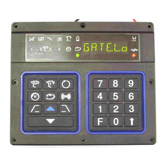
Description The milking point controller (MPCII) is the milker's interface to the ALPRO System. One MPCII is istalled at each cow place in the parlour, and one extra MPCII per parlour for Tandem and Rotary. The front contains a 6 digit display, 14... -
Page 10: Technical Data
DeLaval milking point controller MPCII Product data The large lamp on top of the MPCII informs the milker how the milking of the cow proceeds: Lamp off no milking Lamp on milking is going on Lamp is flashing deviation from normal activities Technical data Voltage: 12 V AC ±... -
Page 11: External Connections
DeLaval milking point controller MPCII Product data External connections 2006-07-20 94381001.pdf 3(94) -
Page 12: Mpcii Connections
DeLaval milking point controller MPCII Product data 1. Duovac 1. Duovac 12. Milk meter 12. Milk meter 2. Regulator block 2. Regulator block A. MM15 A. MM15 3. Gate valve 3. Gate valve B. MM25 B. MM25 4. Rod reader 4. -
Page 13: Mpcii/Alfadast
MPCII/AlfaDast Installation MPCII/AlfaDast Installation 2006-07-20 94381001.pdf 5(94) -
Page 14: Mpcii Connections
MPCII/AlfaDast Installation MPCII connections MPCII With AlfaDast Use a screwdriver, and not a knife to make holes in the grummets. AlfaDast AlfaDast 2006-07-20 94381001.pdf 6(94) - Page 15 MPCII/AlfaDast Installation ———————————————————— Warning! When AlfaDast is connected to ALPRO System, it will operate automatically, and start without any warning. Take care when you are within range of this equipment. ———————————————————— 2006-07-20 94381001.pdf 7(94)
- Page 16 MPCII/AlfaDast Installation 2006-07-20 94381001.pdf 8(94)
-
Page 17: Mpcii/Herringbone
Type Type See section See section With gate valve or gate switch With gate valve or gate switch "MPCII with MM15 and Gate valve or Gate "MPCII with MM15 and Gate valve or Gate switch" switch" L2-L6 L2-L6 Basic functions Basic functions "MPCII with MM15 and Basic functions"... -
Page 18: Gate Definitions
Type Type See section See section With gate valve or gate switch With gate valve or gate switch "MPCII with MM15 and Gate valve or Gate "MPCII with MM15 and Gate valve or Gate switch" switch" R2-R6 R2-R6 Basic functions Basic functions "MPCII with MM15 and Basic functions"... -
Page 19: Gate Switches
MPCII/herringbone Installation Gate switches The two outlet gate switches are defined as left and right respectively, as you see them when looking in the cow traffic direction. Portal ID Left gate switch Left parlour side Right parlour side Right gate... -
Page 20: Mpcii With Mm15 And Basic Functions
MPCII with MM15 and Basic functions Use a screwdriver, and not a knife to make holes in the grummets. If the MPCII is last node on the bus, an end resistor must be connected according to picture El pulsator Duovac ACR - take off... -
Page 21: Mpcii With Mm15 And Gate Valve And Gate Button
MPCII with MM15 and Gate valve and Gate button Use a screwdriver, and not a knife to make holes in the grummets. If the MPCII is last node on the bus, an end resistor must be connected according to picture 2006-07-20 94381001.pdf 13(94) -
Page 22: Mpcii With Mm15 And Gate Valve Or Gate Switch
MPCII with MM15 and Gate valve or Gate switch Use a screwdriver, and not a knife to make holes in the grummets. If the MPCII is last node on the bus, an end resistor must be connected according to picture 2006-07-20 94381001.pdf 14(94) -
Page 23: Mpcii With Fi2
MPCII/herringbone Installation MPCII with FI2 Use a screwdriver, and not a knife to make holes in the grummets. 2006-07-20 94381001.pdf 15(94) -
Page 24: Mpcii With Mm25 Or Fi5
MPCII/herringbone Installation MPCII with MM25 or FI5 Use a screwdriver, and not a knife to make holes in the grummets. Seen from inside DeLaval milk meter MM25 2006-07-20 94381001.pdf 16(94) -
Page 25: Mpcii Addresses
YIELD STORAGE MODE: MILKING TIME ISO STANDARD Set address before you attach MPCII to alcom bus. If a special MPCII is to be installed, set the node address at the highest number. The system processor will now, starting with 80, identify all the other MPCIIs according to: L1–L7: 80, 81, 82, 83, 84, 85, 86... - Page 26 MPCII/herringbone Installation 2006-07-20 94381001.pdf 18(94)
-
Page 27: Mpcii/In-Parlour Feeding
MPCII/In-parlour feeding Installation MPCII/In-parlour feeding Installation 2006-07-20 94381001.pdf 19(94) -
Page 28: Mpcii Connections
MPCII/In-parlour feeding Installation MPCII connections MPCII with Electrically operated In-parlour feeding Use a screwdriver, and not a knife to make holes in the grummets. If the installation includes midiline, also see midiline chapter. For connections on the relay interface box, see separate connection diagram. -
Page 29: Mpcii With Vacuum Operated In-Parlour Feeding
MPCII/In-parlour feeding Installation MPCII with Vacuum operated In-parlour feeding Use a screwdriver, and not a knife to make holes in the grummets. For connections on the vacuum valve, see separate connection diagram. 2006-07-20 94381001.pdf 21(94) - Page 30 MPCII/In-parlour feeding Installation 2006-07-20 94381001.pdf 22(94)
-
Page 31: Mpcii/Midiline
MPCII/MidiLine Installation MPCII connections ———————————————————— Midiline should not be used with ALPRO 6.30, only with ALPRO version 5 processor. ———————————————————— MPCII facing exit Portal ID Right gate Cow traffic switch / valve Connect to D Side switch = open Left parlour side... -
Page 32: Mpcii Facing Entrance
MPCII/MidiLine Installation MPCII facing entrance Portal ID Cow traffic Left gate switch / Side switch = open valve Connect to E Left parlour side Right parlour side Connect to D Right gate Side switch = closed switch / valve 2006-07-20 94381001.pdf... -
Page 33: Mpcii With Basic Functions
MPCII/MidiLine Installation MPCII with Basic functions Use a screwdriver, and not a knife to make holes in the grummets. If the MPCII is last node on the bus, an end resistor must be connected according to picture. 2006-07-20 94381001.pdf 25(94) -
Page 34: Mpcii With Gate Valve Or Gate Switch
MPCII with Gate valve or Gate switch Use a screwdriver, and not a knife to make holes in the If the MPCII is last node on the bus, an end grummets. resistor must be connected according to picture. El pulsator... -
Page 35: Mpcii With Vacuum/Electrically Operated In-Parlour Feeding
MPCII/MidiLine Installation MPCII with Vacuum/Electrically operated In-parlour feeding Use a screwdriver, and not a knife to make holes in the grummets. For connections on the vacuum valve, see separate connection diagram! Side switch Side switch left parlour side = open... - Page 36 MPCII/MidiLine Installation 2006-07-20 94381001.pdf 28(94)
-
Page 37: Mpcii/Rotary
MPCII/Rotary Installation MPCII/Rotary Installation MPCII connections MPCII addresses Address: 88 Address: 87 Address: 89 Address: 86 Address: 85 Address: 90 Address: 91 Address: 84 Address: 92 Address: 83 Address: 93 Address: 82 Address: 94 Address: 81 Address: 95 Address: 80... -
Page 38: Mpcii Each Place
MPCII/Rotary Installation MPCII Each place Use a screwdriver, and not a knife to make holes in the grummets. 2006-07-20 94381001.pdf 30(94) -
Page 39: Mpcii Special - Paralell Rotary
Installation MPCII Special - Paralell rotary Use a screwdriver, and not a knife to make holes in the grummets. If the MPCII is last node on the bus, an end resistor must be connected according to picture. 2006-07-20 94381001.pdf 31(94) -
Page 40: Special Mpcii Hbr
MPCII/Rotary Installation Special MPCII HBR Use a screwdriver, and not a knife to make holes in the grummets. If the MPCII is last node on the bus, an end resistor must be connected according to picture. 2006-07-20 94381001.pdf 32(94) -
Page 41: Mpcii In-Place Id
MPCII/Rotary Installation MPCII In-place ID Use a screwdriver, and not a knife to make holes in the grummets. 2006-07-20 94381001.pdf 33(94) -
Page 42: Mpcii Special Alarm Signals
MPCII/Rotary Installation MPCII Special alarm signals Use a screwdriver, and not a knife to make holes in the grummets. 2006-07-20 94381001.pdf 34(94) -
Page 43: Mpcii/Tandem
A = Left gate B = Right gate The address settings above are for a 2x5 parlour. Start with address 80 on the MPCII nearest exit on left side (L1). Set the address for the special MPCII after the other, in this example address 90. -
Page 44: Mpcii Each Box
MPCII/Tandem Installation MPCII Each box Use a screwdriver, and not a knife to make holes in the grummets. If the MPCII is last node on the bus, an end resistor must be connected according to picture 2006-07-20 94381001.pdf 36(94) -
Page 45: Mpcii Special
MPCII/Tandem Installation MPCII Special Use a screwdriver, and not a knife to make holes in the grummets. If the MPCII is last node on the bus, an end resistor must be connected according to picture 2006-07-20 94381001.pdf 37(94) - Page 46 MPCII/Tandem Installation 2006-07-20 94381001.pdf 38(94)
-
Page 47: Mpcii/Parallel
Type Type See section See section With gate valve or gate switch With gate valve or gate switch "MPCII with MM15 and Gate valve or Gate "MPCII with MM15 and Gate valve or Gate switch" switch" L2-L6 L2-L6 Basic functions Basic functions "MPCII with MM15 and Basic functions"... -
Page 48: Gate Definitions
Type Type See section See section With gate valve or gate switch With gate valve or gate switch "MPCII with MM15 and Gate valve or Gate "MPCII with MM15 and Gate valve or Gate switch" switch" R2-R6 R2-R6 Basic functions Basic functions "MPCII with MM15 and Basic functions"... -
Page 49: Gate Switches
MPCII/parallel Installation Gate switches The two outlet gate switches are defined as left and right respectively, as you see them when looking in the cow traffic direction. Portal ID Left sidee Switch E switch Left parlour side Right parlour side... -
Page 50: Mpcii With Mm15 And Basic Functions
MPCII with MM15 and Basic functions Use a screwdriver, and not a knife to make holes in the grummets. If the MPCII is last node on the bus, an end resistor must be connected according to picture El pulsator Duovac ACR - take off... -
Page 51: Mpcii With Mm15 And Gate Valve And Gate Button
MPCII with MM15 and Gate valve and Gate button Use a screwdriver, and not a knife to make holes in the grummets. If the MPCII is last node on the bus, an end resistor must be connected according to picture 2006-07-20 94381001.pdf 43(94) -
Page 52: Mpcii With Mm15 And Gate Valve Or Gate Switch
MPCII/parallel Installation MPCII with MM15 and Gate valve or Gate switch See also Installation, Portal reader, Connection diagram of the walk-through ID when installed outside the milking parlour. 2006-07-20 94381001.pdf 44(94) - Page 53 MPCII/parallel Installation Use a screwdriver, and not a knife to make holes in the grummets. If the MPCII is last node on the bus, an end resistor must be connected according to picture 2006-07-20 94381001.pdf 45(94)
-
Page 54: Mpcii With Fi2
MPCII/parallel Installation MPCII with FI2 Use a screwdriver, and not a knife to make holes in the grummets. 2006-07-20 94381001.pdf 46(94) -
Page 55: Mpcii With Mm25 Or Fi5
MPCII/parallel Installation MPCII with MM25 or FI5 Use a screwdriver, and not a knife to make holes in the grummets. Seen from inside DeLaval milk meter MM25 2006-07-20 94381001.pdf 47(94) -
Page 56: Mpcii Addresses
YIELD STORAGE MODE: MILKING TIME ISO STANDARD Set address before you attach MPCII to alcom bus. If a special MPCII is to be installed, set the node address at the highest number. The system processor will now, starting with 80, identify all the other MPCIIs according to: L1–L7: 80, 81, 82, 83, 84, 85, 86... -
Page 57: Delaval Milking Point Controller Mpcii
Operation DeLaval milking point controller MPCII Operation Mode description Power-up mode MPCII does nothing but waits for key pressing F79↑ Default address: 1 F79↑ + set the address leads to: Standby mode Two ways to go to mode b: 1) If the milk meter senses any flow, it goes to cleaning mode;... -
Page 58: Display
The command F72↑ always takes you back to standby mode The milking point controller (MPCII) is the milker's interface to the ALPRO System. One MPCII is installed at each cow place in the parlour. Display The display window contains a 4 digits display and 14 indication lights. - Page 59 DeLaval milking point controller MPCII Operation Start/end milking session Manual set/reset forced high vacuum Manual control Acknowledge/override Open/close gate, left Open/close gate, right MidiLine: entrance gate control Remove cluster Release cluster Do not milk Dump milk Treat cow yellow Separate cow...
-
Page 60: Numerical Key Pad
DeLaval milking point controller MPCII Operation Low yield Forced vacuum green Manual control green Remind codes yellow / green / yellow / red Milking phase green Communication interrupted (stand-alone) Lamp off no milking Lamp on milking is going on Lamp is flashing... -
Page 61: Enter Key
- they are confirmed. In stand-alone: the "C" means that the milk weight is stored in the local memory of the MPCII. The local memory can store 32 cows and 32 milk weights. In stand-alone installations is remind LED 1 (yellow) used to indicate that the milk buffer is full. -
Page 62: Start/End Milking
DeLaval milking point controller MPCII Operation set remind code 3. To remove a remind code, press the same keys again. To separate the cow once, press F key, Remind cow key, 4, and ↑. Pressing F key, Remind cow key, 1, 2, 3, and ↑... -
Page 63: Manual Control
MPCII in Tandem stalls. If the Manual control key is pressed together with the Force low to high vacuum key, this MPCII will be locked at high vacuum without automatic cluster removal. The manual control button does not override blocking like the acknowledge/override button. -
Page 64: Release Cluster
F8 has in milk mode. See the function description. Remote lamp The large lamp on top of the MPCII informs the milker how the milking of the cow proceeds: Lamp off no milking... -
Page 65: Treat Cow
DeLaval milking point controller MPCII Operation Treat cow Yellow steady – indicates that the cow need some treatment. Prevents automatic gate opening in a tandem parlour. Separate cow Yellow steady – indicates that the cow should be separated after the milking session. -
Page 66: Remind Codes
Remind codes If one or more of the remind codes are lit for a cow, this means that a remind code is set in the system processor or on the MPCII. 1 = yellow 1 = yellow With AlfaDast installed LED 4 (red) is lit... -
Page 67: F2 - Go To Standby Mode
DeLaval milking point controller MPCII Operation This display is shown. F2 – Go to standby mode Stand-alone To end milking session on this MPCII only, press F, 2, and ↑. 4 dots on the display indicates standby mode. F3 – Milk yield... -
Page 68: F7 - Show Group Number
MPCII. By walking round the parlour and looking at each MPCII display, it is easy to verify if all cows that are being simultaneously milked belong to the same group or not. -
Page 69: F13 - Calving Date Read/Write Function
F13 – Calving date read/write function See function 1:3 in the system processor Pressing F, 1, 3, and ↑ on the MPCII when a cow is identified, shows the last calving date. Pressing ↑ after that shows next calculated heat. -
Page 70: No Available Data
DeLaval milking point controller MPCII Operation by pressing ENTER. Besides reading the ration data, it is possible to programme new rations. Password must be entered prior to programming. Press F, 2, 1, and ↑ Data item # is shown for 0.5 seconds. -
Page 71: F30 - Milking Summary
See function 3:1 on the system processor This function shows milk yield, average milk flow, peak flow, and duration of milking. Press F, 3, 1, and ↑ on the MPCII The milk yield from the latest confirmed milk yield registration is shown. Before milk yield is confirmed, "–"... -
Page 72: F32 - Today's And Yesterday's Milk Yields Read/Write Function
DeLaval milking point controller MPCII Operation The duration of the latest confirmed milk yield registration is shown. Press ↑ on the MPCII to step forward to next data Finish by pressing F and ↑, or wait 30 seconds for time-out. -
Page 73: F43 - Show Last Transponder Read Only
This function shows transponder number for the cow that was last identified in the walk-through ID. The function can be entered on any MPCII on the same side as the walk-through ID. Press F, 4, 3, and ↑ The transponder number is shown in the display Finish by pressing F and ↑, or wait 30... -
Page 74: F62 - General Parameters
DeLaval milking point controller MPCII Operation The MPCII will show: Breeding State, breeding attention and activity attention. ACT. INDEX If this led is set, it will light up if the system shows high activity for this cow. Example: State 2... - Page 75 DeLaval milking point controller MPCII Operation –EF– Enter function After 3 seconds the display shows: PASSWD Enter password 6285 Auto take-off 1 (0 = no, 1 = yes) If processor ver 4.x this must be set ↑ = locally on every MPCII Sweep ↑...
-
Page 76: F63 - General Parameters
(1 = Herringbone, 2 = Rotary, 3 = Tandem, 4 = Midi Line) A special flag indicating that the installed MPCII is a "special MPCII". Is reset by the processor. For Tandem and Rotary only. 0 (0 = milking point MPCII, 1 = special... - Page 77 DeLaval milking point controller MPCII Operation Sweep delay 20 /10 sec (1-9.9) Sweep duration 10/10 sec (0.1-9.9) Low-flow limit 2 /10 kg/min (0.1-0.5) Alfa-dast, time 1 30 sec (15-60) Alfa-dast, time 2 15 sec (1-30) Alfa-dast, time 3 5 sec (1-30)
-
Page 78: Normal Milking
DeLaval milking point controller MPCII Operation F338 Auto-forced high vacuum delay time 60 sec (15-120) An explanation of the above functions under F62 and F63 will follow on the following pages! Normal milking Start High High Activated Not activated Open... -
Page 79: F62 - Options
DeLaval milking point controller MPCII Operation Legend Legend Legend Legend Pre milking phase Pre milking phase Duration of post-milking Duration of post-milking Main milking phase Main milking phase Time between shut-off and cluster Time between shut-off and cluster take-off take-off... -
Page 80: F63 - Limits, Timers, And Options
F325 Direct input of milk weight after take-off. If milk flow indicators have been installed, milk weight can be put into the MPCII (via the numeric key pad) directly after take-off and, as usual, stored after confirmed. This feature is activated by setting this parameter to YES (= 1). - Page 81 Manual forced vacuum button. F323 Post-milking time. This is the duration of the post-milking. See time A in the diagram. This timer will restart every time the MPCII enters post-milking phase. F324 Take-off delay. Delay between vacuum shut-off and retraction. See time B in the diagram.
-
Page 82: F64 - High Vacuum Delay
15 seconds. F71 – Go to milking mode System and stand-alone Pressing F, 7, 1 and ↑ switches this MPCII to milking mode. This display is shown. The MPCII does not know which milking session it is. The system processor will however do this. -
Page 83: F75 - Local Mode
3 = remote release; VT special MPCII left side out/photocell; photocell special MPCII rotary 4 = gate switch, installed at left side of the parlour; VT special MPCII Photocell/right side in 4 = gate switch, installed at left side of the parlour; VT special MPCII Photocell/right side in 5 = gate switch, installed at right side of the parlour;... -
Page 84: F78 - Configuration Check
F78 – Configuration check System This function shows the MPCII place number. See adjoining examples. F79 – Show MPCII's address System and stand-alone Pressing F, 7, 9, and ↑ shows the MPCII's node address for 3 seconds. 2006-07-20 94381001.pdf 76(94) -
Page 85: F82 - Local Cleaning Mode
If you now want to change the address, press 6285 ↑ and write the new address. F82 – Local cleaning mode System and stand-alone Pressing F, 8, 2, and ↑ on the MPCII forces the MPCII to cleaning mode (emergency function). Note! Pulsation ratio always default 65/35 during cleaning mode. -
Page 86: F84 - Open/Close Main Gates
When the call is made from the special MPCII, it will have an effect on both sides of the parlour, both left and right sides. If F85 ↑ is pressed on the special MPCII, both parlour sides are blocked;... -
Page 87: F87 - Water Test
The next call for this function will reset it. The gate button If F86 ↑ is pressed on the special MPCII, no exits will be allowed from any box in the parlour; all boxes are blocked. However, it is... -
Page 88: F88 - Calibration
DeLaval serviceman. F89 – Check calibration System and stand-alone Pressing F, 8, 9, and ↑ in standby mode makes the MPCII ready for checking the calibration. The milk meter is checked for accuracy. Finish, or interrupt by pressing F ↑... -
Page 89: F95 - Reset Software
F95 – Reset software System and stand-alone This function will, if pressed and confirmed with ↑, make software reset (Hot restart). MPCII exits application program and MPCII starts to run boot program. ———————————————————— Warning! If you want to make a reset, program password 6285 ↑... -
Page 90: F97 - Boot Version
MPCII via a relay to the drive control system. A function that can be used for e.g. removal of a cows kick protector before exit. -
Page 91: F371-F374 - Cow Status
DeLaval milking point controller MPCII Operation F371–F374 – Cow status System See function 3:7:1 on the system processor These four functions correspond to function 3:7:1, COW STATUS. Below is shown an example on how the cow status could be set in the system processor. - Page 92 F374 respectively) can also be programmed as short functions: F, Remind Cow button, 1, and ENTER on the MPCII sets "D not milk the cow" for the present milking session and the same session tomorrow and so on until reset.
-
Page 93: F371 - Do Not Milk Status
F371 – Do not milk status System With the same example as in previous section, the settings on the MPCII for this status will be the following: Set the number of days to delay. As it shall start immediately, program 0. -
Page 94: F443 - Calibration Start
This function is used at calibration of the dispenser. Press F443 ↑ and the dispenser starts dispensing one portion. The address of the MPCII is shown in the display. For a complete description of the calibration procedure, see chapter Start-up. -
Page 95: F840 - Opens All Gates
MPC and also a sharper light. New features in the hardware • The size of the MPCII is the same as the old MPC. • The MPCII has only one PCB. •... - Page 96 F-commands. Some old F-commands have changed activity, as described previously in this chapter. The MPCII software is divided into one boot program and one active application program. It has the possibility to store one extra application program as back-up. The...
- Page 97 F76 ↑ 910 ↑ ISO test Pulsator ISO test Pulsator ISO-test. MPCII is set to high vacuum and pulsation using ISO-test. MPCII is set to high vacuum and pulsation using parameter of main milking phase. parameter of main milking phase.
- Page 98 DeLaval milking point controller MPCII Operation application application program application application program page version page version active application program Not active application program 2006-07-20 94381001.pdf 90(94)
-
Page 99: Service
1, and not alcom 2. Exchange the 12V AC terminal from a four connectors to a two. An MPCII with gate function must have Left side gate Right side gate the gate wires connected as shown in the... - Page 100 MPCII in BOOT position for program loading. The MPCII display shows RESET. Sets the MPCII in the BOOT mode for application program loading. During programming the number of files or batches of files are displayed. The amount of data left to download is displayed counting down.
-
Page 101: Troubleshooting
DeLaval milking point controller MPCII Troubleshooting DeLaval milking point controller MPCII Troubleshooting Problem Problem Cause Cause Action Action ERR1: flashing in the display. ERR1: flashing in the display. Unauthorised command. Unauthorised command. Read this MEMO to enter the Read this MEMO to enter the correct F-command. - Page 102 DeLaval milking point controller MPCII Troubleshooting 2006-07-20 94381001.pdf 94(94)
Need help?
Do you have a question about the MPCII and is the answer not in the manual?
Questions and answers