Advertisement
Quick Links
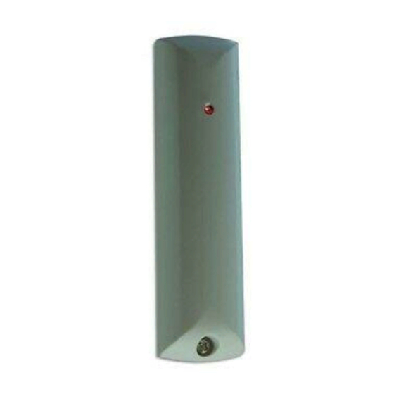
DET-RDCS
Door Contact Shock
Sensor
1. Activity LED
2. Cover screw
3. Aerial
Fig. 1
1. Activity/Learn LED
2. VR1. Sensitivity potentiometer
3. Lid tamper switch
4. Calibration LED
Fig. 2
Fig. 3
© Cooper Security Limited. Every effort has been made to ensure that the contents of this leaflet are correct . However, neither the
authors nor Cooper Security Limited accept any liability for loss or damage caused or alleged to be caused directly or indirectly by this
leaflet. The contents of this leaflet are subject to change without notice. Printed and published in the U.K.
Product Support (UK) Tel: +44 (0)1594 541 978. Available between: 08:30 and 17:00 Monday to Friday,
Product Support Fax: (01594) 545401.
4. Sensors (vibration and magnetic)
5. Transmitter module
6. Battery
5. Battery
6. Back tamper switch
7. Mode jumpers
Note: Range shown for guidance only.
Sensitivity may vary on different surfaces.
Fig. 4
Fig. 5
Fig. 6
Fig. 8
Issue 4
Fig. 7
Fig. 9
19/12/2012 Part No: 12327341
Advertisement

Related Manuals for Cooper Security DET-RDCS

Summary of Contents for Cooper Security DET-RDCS
- Page 1 Fig. 9 © Cooper Security Limited. Every effort has been made to ensure that the contents of this leaflet are correct . However, neither the authors nor Cooper Security Limited accept any liability for loss or damage caused or alleged to be caused directly or indirectly by this leaflet.
- Page 2 The DET-RDCS has several different operating modes. To select the re- to any compatible Cooper Security receiver. The receivers can learn the quired mode you must place the jumpers as follows: unique identity of each DET-RDCS through either an infra-red LED or radio Jumper Function transmissions.
Need help?
Do you have a question about the DET-RDCS and is the answer not in the manual?
Questions and answers