Advertisement
Quick Links
FPC-N34-0643
FPC-N35-0644
BACnet Protonode
LonWorks Protonode
ProtoNode FPC-N34 and ProtoNode FPC-N35
Start-up Guide
For Interfacing Thermal Solutions Product Models
EVA/EVAW/EVO/EVOW with RWF40, RWF55 and RM7800
Controls
To Building Automation Systems:
BACnet MS/TP, BACnet/IP, Modbus TCP/IP, Metasys N2
and LonWorks
APPLICABILITY & EFFECTIVITY
Explains ProtoNode hardware and how to install it.
The instructions are effective for the above as of August 2018.
Document Revision: 7.A
Web Configurator
Template Revision: 70
Advertisement

Summary of Contents for Thermal Solutions ProtoNode FPC-N34 BACnet
- Page 1 FPC-N34-0643 FPC-N35-0644 BACnet Protonode LonWorks Protonode ProtoNode FPC-N34 and ProtoNode FPC-N35 Start-up Guide For Interfacing Thermal Solutions Product Models EVA/EVAW/EVO/EVOW with RWF40, RWF55 and RM7800 Controls To Building Automation Systems: BACnet MS/TP, BACnet/IP, Modbus TCP/IP, Metasys N2 and LonWorks APPLICABILITY & EFFECTIVITY Explains ProtoNode hardware and how to install it.
- Page 2 Thank you for purchasing the ProtoNode for Thermal Solutions. Please call Thermal Solutions for technical support of the ProtoNode product. Sierra Monitor Corporation does not provide direct support. If Thermal Solutions needs to escalate the concern, they will contact Sierra Monitor Corporation for assistance.
- Page 3 Thermal Solutions ProtoNode Start-up Guide Quick Start Guide 1. Record the information about the unit. (Section 3.1) 2. Set the device’s COM settings and Node-ID for each of the devices that are to connect to the ProtoNode. (Section 3.3) 3. FPC-N34: Select the protocol configuration on the S Bank DIP switches. (Section 3.4) 4.
-
Page 4: Table Of Contents
Thermal Solutions ProtoNode Start-up Guide TABLE OF CONTENTS Certifications ............................7 ® BTL Mark – BACnet Testing Laboratory ..................7 LonMark Certification ........................7 Introduction ............................8 ProtoNode Gateway ........................8 Setup for ProtoNode ..........................9 Record Identification Data ......................9 Point Count Capacity and Registers per Device ................ - Page 5 Thermal Solutions ProtoNode Start-up Guide Appendix C. Vendor Information – Thermal Solutions ................. 41 Appendix C.1. RWF40 Modbus RTU Mappings to BACnet, Metasys N2 and LonWorks ....... 41 Appendix C.2. RM7800 Modbus RTU Mappings to BACnet, Metasys N2 and LonWorks ..... 42 Appendix C.3.
- Page 6 Thermal Solutions ProtoNode Start-up Guide LIST OF FIGURES Figure 1: ProtoNode Part Numbers ......................9 Figure 2: Supported Point Count Capacity ....................9 Figure 3: Registers per Device ........................9 Figure 4: COM Settings ..........................10 Figure 5: S Bank DIP Switches ........................11 Figure 6: MAC Address DIP Switches ......................
-
Page 7: Certifications
Thermal Solutions ProtoNode Start-up Guide CERTIFICATIONS ® 1 BTL Mark – BACnet Testing Laboratory The BTL Mark on ProtoNode is a symbol that indicates that a product has passed a series of rigorous tests conducted by an independent laboratory which verifies that the product correctly implements the BACnet features claimed in the listing. -
Page 8: Introduction
INTRODUCTION ProtoNode Gateway The ProtoNode is an external, high performance building automation multi-protocol gateway that is preconfigured to automatically communicate between Thermal Solutions’ products (hereafter called “device”) connected to the ProtoNode and automatically configures them for BACnet MS/TP, BACnet/IP, ®2 ®3... -
Page 9: Setup For Protonode
Thermal Solutions ProtoNode Start-up Guide SETUP FOR PROTONODE Record Identification Data Each ProtoNode has a unique part number located on the side or the back of the unit. This number should be recorded, as it may be required for technical support. The numbers are as follows:... -
Page 10: Configuring Device Communications
Thermal Solutions ProtoNode Start-up Guide Configuring Device Communications 3.3.1 Input COM Settings on All Devices Connected to the ProtoNode • All of the connected serial devices MUST have the same baud rate, data bits, stop bits, and parity settings as the ProtoNode. -
Page 11: Selecting The Desired Protocol Configuration
Thermal Solutions ProtoNode Start-up Guide Selecting the Desired Protocol Configuration • ProtoNode FPC-N34 BACnet units use the “S” bank of DIP switches (S0 – S3) to select the protocol configuration. See the table in Figure 5 for the switch settings to select The OFF position is when the DIP switches are set closest to the outside of the box •... -
Page 12: Bms Network Settings: Mac Address, Device Instance And Baud Rate
Thermal Solutions ProtoNode Start-up Guide BMS Network Settings: MAC Address, Device Instance and Baud Rate 3.5.1 BACnet MS/TP (FPC-N34): Setting the MAC Address for BMS Network • Only 1 MAC Address is set for ProtoNode regardless of how many devices are connected to ProtoNode. -
Page 13: 3.5.2 Bacnet (Fpc-N34): Calculating The Default Device Instance
Thermal Solutions ProtoNode Start-up Guide 3.5.2 BACnet (FPC-N34): Calculating the Default Device Instance • The Device Instance value is automatically generated using the following formula: BACnet Device Instance = (Device Node ID) + (Default Node Offset) NOTE: The default Node Offset is 50,000. -
Page 14: Interfacing Protonode To Devices
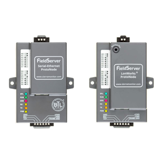
Thermal Solutions ProtoNode Start-up Guide INTERFACING PROTONODE TO DEVICES ProtoNode FPC-N34 and FPC-N35 Showing Connection Ports Figure 9: ProtoNode FPC-N34 (upper) and ProtoNode FPC-N35 (lower) Page 14 of 47... -
Page 15: Device Connections To Protonode
Thermal Solutions ProtoNode Start-up Guide Device Connections to ProtoNode ProtoNode 6 Pin Phoenix connector: • The 6 pin Phoenix connector is the same for ProtoNode FPC-N34 (BACnet) and FPC-N35 (LonWorks). • Pins 1 through 3 are for Modbus RS-485 devices (boiler side). -
Page 16: Wiring Rwf40 To The Protonode
Thermal Solutions ProtoNode Start-up Guide 4.2.1 Wiring RWF40 individually to the ProtoNode • On the RWF40; connect CA on terminal strip to Tx+ on the ProtoNode connector. • Connect CB on terminal strip to Rx- on the ProtoNode connector. •... -
Page 17: Wiring Rm7800 Series To The Protonode
Thermal Solutions ProtoNode Start-up Guide 4.2.3 Wiring RM7800 Display Module individually to the ProtoNode • On the RM7800 Series; connect A on terminal strip to Tx+ on the ProtoNode connector. • Connect B on terminal strip to Rx- on the ProtoNode connector. -
Page 18: End Of Line Termination Switch For The Modbus Rs-485 Network
Thermal Solutions ProtoNode Start-up Guide 4.2.5 End of Line Termination Switch for the Modbus RS-485 Device Network • On long RS-485 cabling runs, the RS-485 trunk must be properly terminated at each end. • The ProtoNode has an End of Line (EOL) blue jumper. The default setting for this Blue EOL switch is OFF with the jumper straddling the pins closest to the inside of the board of the ProtoNode. -
Page 19: Serial Network (Fpc-N34): Wiring Field Port To Rs-485 Network
Thermal Solutions ProtoNode Start-up Guide Serial Network (FPC-N34): W iring Field Port for BACNET RS-485 Network • Connect the BACnet RS-485 network wires to the 3-pin RS-485 connector on ProtoNode FPC- N34 as shown below in Figure Use standard grounding principles for RS-485 GND •... -
Page 20: Power-Up Protonode
Thermal Solutions ProtoNode Start-up Guide Power-Up ProtoNode Check power requirements in the table below: Power Requirement for ProtoNode External Gateway Current Draw Type ProtoNode Family 12V DC/AC 24V DC/AC 30V DC FPC – N34 (Typical) 170mA 100mA 80mA FPC – N34 (Maximum) -
Page 21: Use The Protonode Web Configurator To Setup The Gateway
Thermal Solutions ProtoNode Start-up Guide USE THE PROTONODE WEB CONFIGURATOR TO SETUP THE GATEWAY Connect the PC to ProtoNode via the Ethernet Port • Connect a CAT5 Ethernet cable (Straight through or Cross-Over) between the local PC and the ProtoNode. -
Page 22: Connecting To The Protonode Web Configurator
Thermal Solutions ProtoNode Start-up Guide Connecting to the ProtoNode Web Configurator After setting a local PC on the same subnet as the ProtoNode (Section 5.1), open a web browser on the PC and enter the IP Address of the ProtoNode; the default address is 192.168.1.24. -
Page 23: Figure 22: Web Configurator Showing Available Profiles For Selection
Thermal Solutions ProtoNode Start-up Guide • To add an active profile to support a device, click the Add button under the Active Profiles heading. This will present a drop-down box underneath the Current profile column that lists all the available profiles. -
Page 24: Ethernet Network: Setting Ip Address For The Field Network
Thermal Solutions ProtoNode Start-up Guide Ethernet Network: Setting IP Address for the Field Network • After setting a local PC to the same subnet as the ProtoNode (Section 5.1), open a web browser on the PC and enter the IP Address of the ProtoNode; the default address is 192.168.1.24. -
Page 25: Figure 25: Changing Ip Address Via Fs-Gui
Thermal Solutions ProtoNode Start-up Guide • From the FS-GUI landing page, click on “Setup” to expand the navigation tree and then select “Network Settings” to access the IP Settings menu. (Figure Figure 25: Changing IP Address via FS-GUI • Modify the IP Address (N1 IP Address field) of the ProtoNode Ethernet port. -
Page 26: Bacnet: Setting Node_Offset To Assign Specific Device Instances
Thermal Solutions ProtoNode Start-up Guide BACNET: SETTING NODE_OFFSET TO ASSIGN SPECIFIC DEVICE INSTANCES • After setting a local PC to the same subnet as the ProtoNode (Section 5.1), open a web browser on the PC and enter the IP Address of the ProtoNode. -
Page 27: How To Start The Installation Over: Clearing Profiles
Thermal Solutions ProtoNode Start-up Guide HOW TO START THE INSTALLATION OVER: CLEARING PROFILES • After setting a local PC to the same subnet as the ProtoNode (Section 5.1), open a web browser on the PC and enter the IP Address of the ProtoNode. -
Page 28: Lonworks (Fpc-N35): Commissioning Protonode On A Lonworks Network
Thermal Solutions ProtoNode Start-up Guide LONWORKS (FPC-N35): COMMISSIONING PROTONODE ON A LONWORKS NETWORK Commissioning may only be performed by the LonWorks administrator. Commissioning ProtoNode FPC-N35 on a LonW orks Network During the commissioning process, the LonWorks administrator may prompt the user to hit the service pin on the ProtoNode FPC-N35 at a specific point (this step occurs at different points of the commissioning process for each LonWorks network management tool). -
Page 29: Figure 29: Sample Of Fserver.xif File Generated
Thermal Solutions ProtoNode Start-up Guide • Open a web browser and go to the following address: [IP Address of ProtoNode]/fserver.xif Example: 192.168.1.24/fserver.xif • If the web browser prompts to save the file, save the file onto the PC. If the web browser displays the xif file as a web page, save the file onto the local PC as “fserver.xif”. -
Page 30: Bacnet Explorer Ng
Thermal Solutions ProtoNode Start-up Guide BACNET EXPLORER NG A typical working example of a BACnet Explorer NG on a BACnet Network: Modbus RTU up to 32 BACnet MS/TP devices Modbus RTU BACnet Explorer NG up to 32 BACnet MS/TP devices... -
Page 31: Appendix A. Troubleshooting
Thermal Solutions ProtoNode Start-up Guide Appendix A. Troubleshooting Appendix A.1. Lost or Incorrect IP Address • Ensure that FieldServer Toolbox is loaded onto the local PC. Otherwise, download the FieldServer-Toolbox.zip via the Sierra Monitor Resource Center Software Downloads. • Extract the executable file and complete the installation. -
Page 32: Appendix A.2. Viewing Diagnostic Information
Thermal Solutions ProtoNode Start-up Guide Appendix A.2. Viewing Diagnostic Information • Type the IP Address of the ProtoNode into the web browser or use the FieldServer Toolbox to connect to the ProtoNode. • Click on Diagnostics and Debugging Button, then click on view, and then on connections. -
Page 33: Appendix A.3. Check Wiring And Settings
Thermal Solutions ProtoNode Start-up Guide Appendix A.3. Check Wiring and Settings • No COMS on Modbus RTU side. If the Tx/Rx LEDs are not flashing rapidly then there is a COM issue. To fix this, check the following: Visual observations of LEDs on ProtoNode (Appendix A.4) -
Page 34: Appendix A.4. Led Diagnostics For Communications Between Protonode And Devices
Thermal Solutions ProtoNode Start-up Guide Appendix A.4. LED Diagnostics for Communications Between ProtoNode and Devices See the diagram below for ProtoNode FPC-N34 and FPC-N35 LED Locations. Diagnostic LEDs Description The SPL LED will light if the unit is not getting a response from one or more of the configured devices. -
Page 35: Appendix A.5. Take Diagnostic Capture With The Fieldserver Toolbox
Thermal Solutions ProtoNode Start-up Guide Appendix A.5. Take Diagnostic Capture with the FieldServer Toolbox • Once the Diagnostic Capture is complete, email it to technical support. The Diagnostic Capture will accelerate diagnosis of the problem. • Ensure that FieldServer Toolbox is loaded onto the local PC. Otherwise, download the FieldServer-Toolbox.zip via the Sierra Monitor Resource Center... - Page 36 Thermal Solutions ProtoNode Start-up Guide Ensure “Full Diagnostic" is selected (this is the default) NOTE: If desired, the default capture period can be changed. Click on “Start Diagnostic” When the capture period is finished, the “Diagnostic Test Complete” window will appear...
- Page 37 Thermal Solutions ProtoNode Start-up Guide • Step 2: Send Log Once the diagnostic test is complete, a .zip file is saved on the PC Choose “Open” to launch explorer and have it point directly at the correct folder Send the Diagnostic zip file to technical support (jvino@tssalesco.com)
-
Page 38: Appendix A.6. Take A Diagnostic Capture Via Fs-Gui
Thermal Solutions ProtoNode Start-up Guide Appendix A.6. Take a Diagnostic Capture via FS-GUI Diagnostic Capture via FS-GUI is only available on FieldServers with a bios updated/released on November 2017 or later. Completing a Diagnostic Capture through the FieldServer allows network connections (such as Ethernet and Wi-Fi) to be captured. -
Page 39: Appendix B. Additional Information
Thermal Solutions ProtoNode Start-up Guide Appendix B. Additional Information Appendix B.1. Update Firmware To load a new version of the firmware, follow these instructions: 1. Extract and save the new file onto the local PC. 2. Open a web browser and type the IP Address of the FieldServer in the address bar. -
Page 40: Appendix B.3. Securing Protonode With Passwords
Thermal Solutions ProtoNode Start-up Guide Appendix B.3. Securing ProtoNode with Passwords Access to the ProtoNode can be restricted by enabling a password on the FS-GUI Passwords page – click Setup and then Passwords in the navigation panel. There are 2 access levels defined by 2 account names: Admin and User. -
Page 41: Appendix C. Vendor Information - Thermal Solutions
NOTE: All Modbus TCP/IP registers are the same as the Modbus RTU registers for the serial device. If this point list is needed, contact Thermal Solutions technical support. The Modbus TCP/IP node address of the device is also the same as the Modbus RTU node address. -
Page 42: Appendix C.2. Rm7800 Modbus Rtu Mappings To Bacnet, Metasys N2 And Lonworks
Thermal Solutions ProtoNode Start-up Guide Appendix C.2. RM7800 Modbus RTU Mappings to BACnet, Metasys N2 and LonWorks BACnet BACnet N2 Data Point Name LonWorks Name LonWorks SNVT Object Type Object ID Type Address Com Status nvoComStatus_XXX SNVT_switch Flame Signal nvoFlameSig_XXX... -
Page 43: Appendix D. "A" Bank Dip Switch Settings
Thermal Solutions ProtoNode Start-up Guide Appendix D. “A” Bank DIP Switch Settings Appendix D.1. “A” Bank DIP Switch Settings Address Address Page 43 of 47... - Page 44 Thermal Solutions ProtoNode Start-up Guide Address Address Page 44 of 47...
- Page 45 Thermal Solutions ProtoNode Start-up Guide Address Address Page 45 of 47...
-
Page 46: Appendix E. Reference
Thermal Solutions ProtoNode Start-up Guide Appendix E. Reference Appendix E.1. Specifications ProtoNode FPC-N34 ProtoNode FPC-N35 One 6-pin Phoenix connector with: One 6-pin Phoenix connector with: RS-485 port (+ / - / gnd) RS-485 port (+ / - / gnd) Power port (+ / - / Frame-gnd) -
Page 47: Appendix F. Limited 2 Year Warranty
Thermal Solutions ProtoNode Start-up Guide Appendix F. Limited 2 Year Warranty Sierra Monitor Corporation warrants its products to be free from defects in workmanship or material under normal use and service for two years after date of shipment. Sierra Monitor Corporation will repair or replace any equipment found to be defective during the warranty period.
Need help?
Do you have a question about the ProtoNode FPC-N34 BACnet and is the answer not in the manual?
Questions and answers