Advertisement
Quick Links
1 0 6 1 S
8 0 0 E
O U T H
A S T
Overview
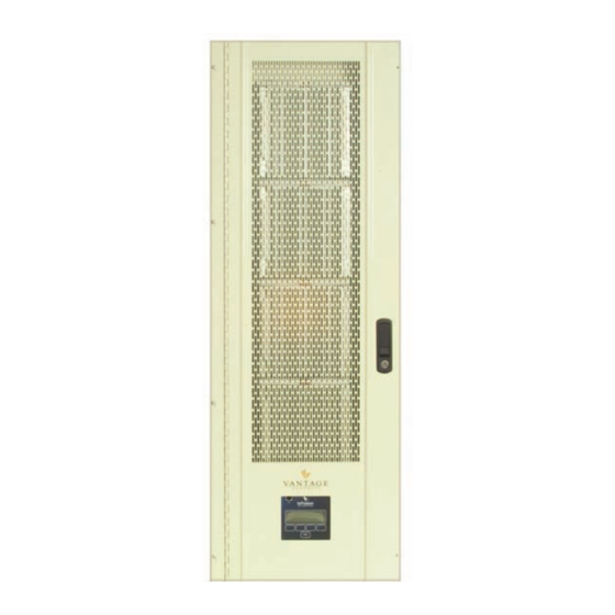
The Vantage Power Enclosure is the hub of a Vantage
automation system. The enclosure is a connection point for loads
that need to be dimmed or toggled. The enclosure may contain
standard dimming modules, electronic dimming modules and
relay modules or any combination. All connections are easily
made via clearly labeled connectors. High voltage, low voltage,
Secondary enclosures, RS-232 and RS-485 (RS-485
connections to InFusion enclosures only) communication devices
may all be wired back to this control point.
Main and Secondary Power Enclosures are designed to fit
perfectly between conventional framing, however, the enclosures
may also be surface mounted. Four Main Power Enclosure and
four Secondary Power Enclosure models are available, the
MPER/SPER-4 or MPES/SPES-4, is a four module enclosure
the MPER/SPER-2 and MPES/SPES-2, is a two module
enclosure. The "R" is for recessed and the "S" is for surface
mount. The same enclosure is used for InFusion and QLink
Systems. The Main Terminal Board or the Secondary Terminal
Board is the only differing component when ordered for an
InFusion System or a QLink system. For an InFusion System the
part number adds "–IC36" or "–IC24" to the end of the part
number.
See: Enclosure Mounting Instructions, (below).
Specifications
Dimensions HWD
Weight
Number of Modules
Line Feed Terminals
(breaker feeds)
Load Terminals (loads out)
Neutral Terminals
Ground Bar Terminals
*Flash Memory
(MPER-QLink System Only)
Cover
UL and CUL listed
*InFusion Enclosures do not have a flash memory chip in the
enclosure it has been replaced with an MMC/SD flash card
reader in the InFusion Controller.
System Requirements
Wire.................. copper wire, minimum of 80°C / 176°F insulation
Ventilation .................................. maintained 36" frontal clearance
Ambient Operating Temperature ..................... 0-40°C / 32-104°F
Ambient Operating Humidity.................... 5-95% non-condensing
Enclosure Mounting Instructions
Installation of Vantage products should be performed or
supervised by a Certified Vantage Installer.
1.
Do not mount enclosures in attics, garages, or
crawlspaces, unless room is properly ventilated to
conform with room temperature and humidity
requirements set forth (above).
• O
, U
8 4 0 9 7 • T
R E M
T A H
E L E P H O N E
P o w e r E n c l o s u r e — M P E R / S P E R ( S ) - 2 / 4 - ( I C 3 6 / 2 4 )
M(S)PER-2
M(S)PER-4
25"x14.5"x4"
42"x14.5"x4"
-or-
-or-
635mm
1066mm
368mm
368mm
101mm
101mm
15 lbs
26 lbs
-or-
-or-
6.8 kg
11.8 kg
2
8
16
16
32
24
48
20
40
yes
yes
vented, hinged,
vented, hinged, self
self latching and
latching and locking
locking
yes
yes
I n s t a l l a t i o n
8 0 1 . 2 2 9 . 2 8 0 0 • F
A C S I M I L E
2.
Mount enclosure a minimum of 18" from ceiling and
floor.
3.
National Electrical Code requires a minimum frontal
clearance of 36" for the enclosure.
4.
Use eight 1½" screws for mounting MPER-4. Use four
1½" screws for MPER-2.
5.
The surface mount enclosure (MPES-2/4) lid is
designed to mount flush to the enclosure, so that
multiple enclosures can be placed next to each other.
6.
The recessed mount enclosure lid (MPER-2/4) has a
1/2" lip that extends past the enclosure side,
concealing the edge of the enclosure next to the wall.
Wiring Instructions
Each enclosure has the following conduit knockouts:
Top and Bottom:
21 - 1/2" and 4 - 3/4" knockouts for high voltage wiring.
In the bottom of the enclosure it is recommended that low
voltage knockouts in the center section be used for low voltage
runs for complete isolation from high voltage runs. A metal cage
surrounds the low voltage area of the enclosure.
Vantage recommends that the Main Controller be wired to a
separate circuit breaker. It should not share a circuit breaker with
any load modules.
If the installation has more than one enclosure, Vantage
recommends that the Main and Secondary enclosures be
connected to the same circuit breaker. This suggestion is based
on the enclosures being in close proximity to each other. If the
installation has multiple enclosure groups that are far apart it
might not be feasible for the enclosures to share the same circuit
breaker.
4
NOTE: InFusion Systems do not require a Secondary Controller
or power to the Secondary Enclosure Terminal Board.
QLink Systems with all new modules (MDS and MDR) models do
not require a Secondary Controller or power to the Slave
Terminal Board. For older QLink Systems using SD-Series, ED-
Series and AR-Series modules, Vantage recommends that the
Slave Controller be wired to a separate circuit breaker. It should
not share a circuit breaker with any load modules. SD, ED, and
AR-Series modules are not compatible with 36Volt InFusion
Systems but will work with 24Volt InFusion Systems. Older
QLink Systems with Secondary enclosures containing these type
modules must use the QLink system (slave) terminal board and
Slave Controller even when converted to an Infusion System.
Main Controller to Main Controller Wiring
When connecting multiple Main Enclosures, Vantage
recommends the use of 16-18 AWG 2-conductor, twisted pair,
non-shielded wire from Main Enclosure to Main Enclosure. This
is a polarized connection with "+" and "–" screw terminals for two
runs of wire. The beginning and ending Main Enclosures will use
one set of screw terminals at the Controller Bus terminals and all
Main Enclosures in-between will use both sets of screw terminals
on the Controller Bus terminals, i.e., one set of screws
connecting from the previous enclosure and the other set of
screws continuing to the next enclosure. The maximum wire
length for all Controllers connected together on one bus should
not exceed 2,000ft. in InFusion Systems or 1,000ft. in QLink
Systems using the above wire specification.
8 0 1 . 2 2 4 . 0 3 5 5 • w w w . v a n t a g e c o n t r o l s . c o m
Advertisement

Summary of Contents for Vantage Controls MPER-2
- Page 1 The recessed mount enclosure lid (MPER-2/4) has a 1/2" lip that extends past the enclosure side, Main and Secondary Power Enclosures are designed to fit concealing the edge of the enclosure next to the wall.
- Page 2 NOTE: InFusion Systems can also use Ethernet connections for RS-485 Connections for InFusion Controller to Controller communication. Please see the InFusion The Main Enclosure Terminal Board has two RS-485 ports. Controller instruction sheet. These ports are shared with Secondary Enclosure ports 3 and 4. The ports may not be used for Secondary Enclosure support and RS-485 support simultaneously.
- Page 3 InFusion and QLink Enclosures are identical except the Terminal Boards in the bottom of each Enclosure:...
- Page 4 Controller Locking Screws - Use Phillips #2 Screwdriver: InFusion Main Enclosure Terminal Board Terminations: QLink Master Terminal Board Terminations:...
- Page 5 InFusion Override and Secondary Wiring Examples: QLink Override and Secondary Wiring Examples:...
- Page 6 Detail Wiring InFusion Main Enclosures to InFusion Secondary Enclosures (See wire specifications above) Enclosure Assembly: 39209 / InFusion and QLink compatible Warranty at: http://www.vantagecontrols.com/warranty ©Vantage Controls...
Need help?
Do you have a question about the MPER-2 and is the answer not in the manual?
Questions and answers