
Summary of Contents for Airtec RE-46
- Page 1 PROFINET fieldbus instructions Valve Terminal RE-46 PROFINET Additional fieldbus instructions to the user manual RE-46 Version: 12/20 Art.-No.: 54-RE-46-EN-PN...
-
Page 2: Table Of Contents
Electrical data _____________________________________________ 7 Connections and elements of the RE-46 PROFINET _____________ 8 Connections of the RE-46 PROFINET (Front view) ......8 Indicators and elements of the RE-46 PROFINET (top view) ..10 Indictator LEDs fieldbus status (PROFINET) ........11 3.3.1 Inicator LEDs for Link &... - Page 3 Used abbreviations and their explanations API ................. Application Process Identifier Byte wise ............. Data is handled as units of 1 byte (8 bits) Controller .................... PROFINET Master DAP .....................Data Access Point Device ....................PROFINET Slave EMC ................... electromagnetic compliance FB ........................Fieldbus GSDML-File ........
- Page 4 Used depictions in these instructions Normal text Normal text Text + bold face Emphasis Text + bold face + italics Proper names Hyperlinks Reference to other text areas ADVICE/HINT: Text…. Advices in a green box do not have any safety-relevant importance. The background colour is just a help to find important information easier.
-
Page 5: General
General The pneumatical data and the mounting of the RE-46 PROFINET are identical to the RE- 46 Multipin version. WARNING: For installation and commissioning of the pneumatic part of the valve ter- minal, please read the “Instructions for use Valve terminal RE-46”... -
Page 7: Electrical Data
Electrical data RE-46 PROFINET Parameter Value Valve Stations 6, 8, 10, 12 ... 24 Fieldbus connectors 2 x M12 5-pin female D-coded Power connector M12 5-pin male A-coded Power consumption (each sole- 1 W (solenoid) plus 0,3 W for the status LED... -
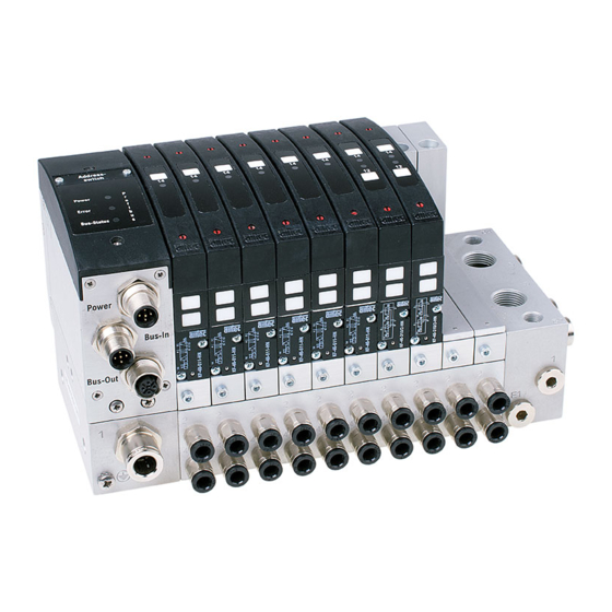
Page 8: Connections And Elements Of The Re-46 Profinet
Connections and elements of the RE-46 PROFINET 3.1 Connections of the RE-46 PROFINET (Front view) Flange header M12 5-pin A-coded (POWER) Designation Description +24V Supply voltage for bus electronics Fuse: 1A slow blow +24V_1 Supply voltage for valves 1-12 (solenoids1-24) - Page 9 Secondary air supply has to be connected, if the valve terminal has an internal pressure zone splitting (option) or if very high air flow rates are required. (see chapter 8.4 in "Instructions for use Valve terminal RE-46")
-
Page 10: Indicators And Elements Of The Re-46 Profinet (Top View)
10 Cover: This cover normally can be removed to set manually the fieldbus address of the RE-46. For PROFINET no manual address setting is required! Anyway this cover may not be removed to guarantee IP65 protection code. 11 Indicator LEDs bus status (PROFINET): These LEDs signalize the status of the bus system and the valve terminal. -
Page 11: Indictator Leds Fieldbus Status (Profinet)
3.3 Indicator LEDs fieldbus status (PROFINET) These indicator LEDs can be found on the left top side of the RE-46 Indicator LEDs (PROFINET): Designation Color Description Supply voltage LED 24V_1 green +24V for fieldbus electronics 24V_2 green Supply voltage LED... -
Page 12: Inicator Leds For Link & Activity Status (P1 L/A & P2 L/A)
Indicator LEDs for Link & Activity Status (P1 L/A & P2 L/A) 3.3.1 Indicator LEDs for module status (MD OK & MD ERR) 3.3.2 Indicator LEDs for PROFINET Status (FB OK & FB ERR) 3.3.3... -
Page 13: Arrangement Of Valves + Solenoids
3.4 Arrangement of valves + solenoids The following drawing shows the arrangement of valves + solenoids: Solenoid 1 Solenoid 39 Solenoid 40 Solenoid 2 Group n +1 Group n Group 1 Group 2 Group 3 Station: Slot for a monostable, bistable or center position valve. Depending on the valve type, either one or two solenoids can be present. -
Page 14: Controlling The Valves By A Plc Or Ipc
3.5 Controlling the valves by a PLC or IPC In the table below you will find the assignment of bits and bytes of the output data to the valves / solenoids: Group 1 (output byte 1) 2 (output byte 2) 3 (output byte 3) Station Solenoid... -
Page 15: Installation Of The Re-46 Canopen
IP65 can only be achieved if all air connections are plugged either with a tube or a sealing plug. Connection cables must be plugged in also and should fulfill at least the same protection code (IP65 or higher). AIRTEC offers ready-to-use standard cables in different lengths for this purpose as accessories. ADVICE: When using cables of low quality or with reduced IP protection code the valve ter- minal might be damaged by penetration of dust and/or liquids. -
Page 16: Power Cable
4.2 POWER cable Standard sensor cables with 5-pin circular female connector, M12 thread, A- coded Straight or angled connectors can be used Diameter of each conductor strand min. 0,25mm² (AWG 24) Cables can be shielded or not shielded. A shield is not absolutely necessary but improves the EMC performance of the valve terminal. -
Page 17: Profinet Cables
Threaded or fast-lock Straight or angled versions can be used (straight is recommended The RE-46 has 2 PROFINET ports with an integrated Ethernet Switch (Fieldbus cable can be looped from one to the next device) Category 5 compliant to IEC 11801 ... -
Page 18: Fieldbus Topology
Fieldbus topology Structure of the fieldbus 4.5.1 The structure of the PROFINET network is flexible. All types of network structures are supported (linear bus, star or ring structures). For the use in a linear bus structure the PROFINET cable is looped from one to the next device. -
Page 19: Emc-Considerations
WARNING: Use certified PROFINET cable links only! The maximum length of one cable link might not exceed 100m (328 feet) Detailed planning & installation hints can be found here: https://www.profibus.com/download/profinet-installation-guidelines/ EMC-Considerations 4.5.2 In industrial environment, the grounding and shielding of the cables and devices is very important for safe operation. -
Page 20: Commissioning The Re-46 Profinet
Commissioning the RE-46 PROFINET 5.1 Electrical connections Switch off the fieldbus segment where the RE-46 PROFINET should be installed. Prepare the power cable (+24V DC) connection, but do not yet connect it! POWER cable 24V Fieldbus Port 1 Fieldbus Port 2... - Page 21 Connect the PROFINET inbound cable to the Port 1 connector 2 of the RE-46 and the fieldbus outbound cable to the Port 2 connector 3 . In star structures the Port 2 is not used. Tighten the fixing nuts of the cable only slightly with your fingers. Do not use any tools like a pipe wrench or combination pliers.
-
Page 22: Commissioning The Profinet Controller
5.2 Commissioning the PROFINET Controller Below you will find the steps to the commissioning of the RE-46 in combination with the TwinCAT System Manager of BECKHOFF and EL xxxx PROFINET Con- troller. The PLC consists of a PROFINET Controller and is linked with an Industrial PC (IPC) via EtherCAT. - Page 23 Restart TwinCAT in configura- tion mode? Picture 3 (MessageBox) Confirm the restart with OK. Step 2: Scanning and inserting the PROFINET Controller I/O-Devices… Add device Search for devices… Picture 4 (Search for devices) Click with the right mouse button on IO-Devices\Search for devices for an auto- matic scan of your PROFINET Controller.
- Page 24 1 New I/O-Device found Picture 6 (Selecting the LAN connection) Choose the LAN connection where your PROFINET Controller is connected and confirm with OK. Scanning for new boxes Picture 7 (MessageBox) Activate free run Picture 8 (MessageBox to start Free Run mode) Confirm the next two MessageBoxes with YES to attach your PROFINET Con- troller (in this case the EL6631) and to activate it in Free Run mode.
- Page 25 I/O-Devices… Picture 9 (Found I/O-Devices) After a successful scan the new I/O-Device will be shown under I/O-Configura- tion. In this case: The EtherCAT coupler -> EK1100 The PROFINET IO Controller -> EL6631 The Termination Device -> EL9011 Add device Picture 10 (Add device) Click with the right mouse button on I/O-Devices and select Add device to at- tach the PROFINET Controller EL6631.
-
Page 26: Commissioning The Profinet-Device
Device 1 (EL6631) Scanning for boxes… Picture 12 (Insert the RE46-PROFINET Device) After this step click with the right mouse button on Device1(EL6631)\Scan for boxes… to scan for the RE-46 PROFINET device. Make sure the RE-46 is con- nected and under power. - Page 27 The default device name is „re46-profinet“. Select the device in the list [1] and then click on Add Devices [2]. Picture 14 (Scan real config.) Confirm the next MessageBox with YES to finally attach der RE-46 PROFINET. Then close the scanning window by clicking the x in the right upper corner.
- Page 28 - Solenoid 25-32 (valve outputs) Slot#5 - Solenoid 33-40 (valve outputs) Slot#6 - Solenoid 41-48 (valve outputs) Depending on the size of your RE-46 PROFINET the number of outputs will dif- fer: HINTS: For valve terminals with...
- Page 29 Step 4: Creating a software task In order to exchange process data between the RE-46 PROFINET and your soft- ware application on the PLC/IPC, a software task has to be created on the Twin- CAT System Manger. Inside this task, some variables have to be created to handle the data.
- Page 30 Picture 18 (Task settings) In Picture 18 you can see an example of the task settings. They can be modified by right-clicking on the task. HINT: This is only an example. The correct settings for your tasks might be different from these.
- Page 31 Step 5: Creating the variables and shortcuts to the hardware HINTS: The number of the required variables depends on your application. These varia- bles shown here are just an example how to do it. For more details see again: Beckhoff TwinCAT: http://infosys.beckhoff.de/index.php?content=../content/1031/tcsystemman- ager/basics/tcsysmgr_mappvar.htm&id= Beckhoff Infosys under TwinCAT 2/TwinCAT System Manager/Operation/Variables...
- Page 32 Picture 20 (Configuratoin off variables) Enter the name for the next variable, i. e. OUT 09-16 [1]. Select the type of variable UINT8 (unsigned integer 8 bits) [2]. Confirm with OK [3]. Repeat these steps until you have created as many variables as required to con- trol all outputs.
- Page 33 Picture 21 (Create shortcut) Now you have to create a shortcut between the variables in the task PROFINET and the physical outputs of the RE-46 PROFINET: Select the first API Slot #1, open the details by clicking on the node, then select the submodule (Subterm 1), then select Outputs and then 1 Byte Data Item [1].
- Page 34 (solenoids), then confirm with OK. Repeat this step until all physical outputs are attached to variables. See also chapter 3.4 how to control the solenoids of the RE-46 PROFINET. Step 6: Activating the new configuration Activate configuration Picture 23 (Activating the configuration) In order to send the new hardware configuration to your PROFINET controller, you have to click on the button Activate Configuration.
- Page 35 Picture 24 (Creating the new variables) Picture 25 (Acitvate the new configuration) Picture 26 (Restart the controller in run mode) Please confirm these 3 MessageBox with YES resp. OK. The controller will re-start then and should go into run mode.
- Page 36 Step 7: Checking the PROFINET fieldbus connection After the re-start the controller should establish a PROFINET connection between the controller and the device. To check the correct function have a look at the LEDs on top of the bus system. After a few seconds you should see the following LEDs: LED Designation Color State...
- Page 37 Please see the following link for more details: Beckhoff TwinCAT: http://infosys.beckhoff.de/index.php?content=../content/1031/tcsystemman- ager/basics/tcsysmgr_mappvar.htm&id= Step 8: Control process data manually In order to test the outputs of the RE-46 manually and to switch single solenoids, please follow these steps: Write… Outputs Picture 28 (Modifying process data) Select Additional Tasks / PROFINET and then one of the outputs you want to modify [1].
- Page 38 Picture 29 (Write process data) Enter in the Set Value Dialog the output value you want to write to your process data and then select the button OK. Example: The hexadecimal value 0x55 will activate all odd solenoids on the first 4 valves, e.
-
Page 39: Trouble Shooting
5.4 Trouble shooting If problems or malfunctions appear on your RE-46 PROFINET, you can use the following table to check for possible causes and solutions. HINT: Please always watch the LED indicators on top of the bus system. They deliver important information for possible failure causes. -
Page 40: Contact And Support
6 Contact and support AIRTEC Pneumatic GmbH Westerbachstraße 7 D-61476 Kronberg Germany +49 61 73 – 95 62-0 Phone +49 61 73 – 95 62-49 http://ww.airtec.de E-Mail: Info@airtec.de...
Need help?
Do you have a question about the RE-46 and is the answer not in the manual?
Questions and answers