Table of Contents
Advertisement
Advertisement
Table of Contents

Summary of Contents for WAGO 758-919
- Page 1 Manual 758-919 Wireless Access Point Version 1.0.0...
- Page 2 We wish to point out that the software and hardware terms as well as the trademarks of companies used and/or mentioned in the present manual are generally protected by trademark or patent. WAGO is a registered trademark of WAGO Verwaltungsgesellschaft mbH. Manual Version 1.0.0...
-
Page 3: Table Of Contents
Table of Contents 758-919 Wireless Access Point Table of Contents Notes about this Documentation ............. 5 Copyright ....................5 Symbols ....................6 Number Notation ..................8 Font Conventions ................... 8 Important Notes ..................9 Legal Bases .................... 9 2.1.1 Subject to Changes ................9 2.1.2... - Page 4 Table of Contents 758-919 Wireless Access Point 5.2.11 Configurations via AT Commands ............ 46 5.2.12 System Settings ................47 Factory Restore ..................48 Appendix ....................49 Configuration Examples ................ 49 Ethernet Bridge via WLAN or Bluetooth ® (Easy Config) ....49 6.1.1...
-
Page 5: Notes About This Documentation
Manual by third parties that violate pertinent copyright provisions is prohibited. Reproduction, translation, electronic and phototechnical filing/archiving (e.g., photocopying) as well as any amendments require the written consent of WAGO Kontakttechnik GmbH & Co. KG, Minden, Germany. Non-observance will involve the right to assert damage claims. Manual... -
Page 6: Symbols
Notes about this Documentation 758-919 Wireless Access Point Symbols Personal Injury! Indicates a high-risk, imminently hazardous situation which, if not avoided, will result in death or serious injury. Personal Injury Caused by Electric Current! Indicates a high-risk, imminently hazardous situation which, if not avoided, will result in death or serious injury. - Page 7 Notes about this Documentation 758-919 Wireless Access Point Additional Information: Refers to additional information which is not an integral part of this documentation (e.g., the Internet). Manual Version 1.0.0...
-
Page 8: Number Notation
Notes about this Documentation 758-919 Wireless Access Point Number Notation Table 1: Number Notation Number Code Example Note Decimal Normal notation Hexadecimal 0x64 C notation Binary '100' In quotation marks, nibble separated '0110.0100' with dots (.) Font Conventions Table 2: Font Conventions Font Type Indicates Names of paths and data files are marked in italic-type. -
Page 9: Important Notes
These modules contain no parts that can be serviced or repaired by the user. The following actions will result in the exclusion of liability on the part of WAGO Kontakttechnik GmbH & Co. KG: •... - Page 10 Important Notes 758-919 Wireless Access Point Further details are given in the contractual agreements. Please send your request for modified and new hardware or software configurations directly to WAGO Kontakttechnik GmbH & Co. KG. Manual Version 1.0.0...
-
Page 11: Special Use Conditions For Ethernet Devices
Please note the following when using ETHERNET devices in your system: • Do not connect control components and control networks directly to an open network such as the Internet or an office network. WAGO recommends putting control components and control networks behind a firewall. •... -
Page 12: Storage, Assembly And Transport
Important Notes 758-919 Wireless Access Point Storage, Assembly and Transport Whenever possible, the components are to be stored in their original packaging. Likewise, the original packaging provides optimal protection during transport. When assembling or repacking the components, the contacts must not be soiled or damaged. -
Page 13: Safety Advice (Precautions)
Important Notes 758-919 Wireless Access Point Safety Advice (Precautions) For installing and operating purposes of the relevant device to your system the following safety precautions shall be observed: Always use voltage sources with current limitation/safety extra-low voltage! Only use power supply sources based on IEC/EN60950 Section 2.5 “Power sources with limited output”... - Page 14 Important Notes 758-919 Wireless Access Point Replace defective or damaged devices! Replace defective or damaged device (e.g., in the event of deformed contacts), since the long-term functionality of fieldbus station involved can no longer be ensured. Protect the components against materials having seeping and insulating...
- Page 15 Important Notes 758-919 Wireless Access Point Do not open the enclosure! Never open the enclosure. Opening of the enclosure will nullify the guarantee, legal warranty and authorization for use. EXPLOSION HAZARD! Substitution of any components may impair suitability for the explosive environment.
-
Page 16: Device Description
Device Description 758-919 Wireless Access Point Device Description General Description As a Wireless Access Point (WAP), the device makes it possible to integrate conventional ETHERNET devices in a wireless network. For this purpose, the device has a wired ETHERNET interface and another interface for radio communication. - Page 17 Device Description 758-919 Wireless Access Point Restrictions • The Bluetooth ® PAN (Personal Area Network) may not work with your own devices. The reason is the different implementation of Bluetooth ® various manufacturers. • 5 GHz WLAN cannot be used with 2.5 GHz WLAN or Bluetooth ®...
-
Page 18: View
Device Description 758-919 Wireless Access Point View Figure 2: View Table 3: Legend for Figure “View” Pos. Description Details see Section Antenna for WiFi and Bluetooth ® “Technical Data” Power Connector (Art.-Nr. 2734-103/107-000) - ETHERNET Connector (RJ45, POE) “Connectors” RESET Button “RESET Button”... -
Page 19: Labeling
Device Description 758-919 Wireless Access Point Labeling The device MAC address is included with other data on the device: Figure 3: Marking – Type Plate Part 1 (Example) Figure 4: Marking – Type Plate Part 2 (Example) Table 4: Legend for Figure “Label (Example) „Serial NO“... -
Page 20: Connectors
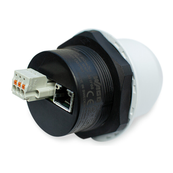
Device Description 758-919 Wireless Access Point Connectors Figure 5: Connectors Make sure that the power supply is connected correctly! Connecting power with reverse polarity or using the wrong type of power supply may damage the equipment. Make sure that the power supply is connected correctly and of the recommended type! See also Chapter „Technical Data“, regarding power supply requirements... -
Page 21: Rj45 Led Indicators
Device Description 758-919 Wireless Access Point RJ45 LED Indicators Figure 6: RJ45 LED indicators Table 7: LED A – LINK/ACTIVITY LED A – LINK/ACTIVITY Function No Ethernet link or no power Yellow Ethernet link established Yellow, flashing Ethernet traffic Table 8: LED B – STATUS LED B –... -
Page 22: Reset Button
Device Description 758-919 Wireless Access Point RESET Button Figure 7: RESET Button The RESET button is located on the bottom of the unit. When the unit is powered on, press and hold RESET for > 10 seconds and then release it to reset to the factory default settings. -
Page 23: Technical Data
Device Description 758-919 Wireless Access Point Technical Data 3.7.1 Hardware Specifications Table 9: Hardware Specifications Order Code 758-919 Color White top and black base Wired interface type ETHERNET (RJ45 PoE) ETHERNET connector RJ45 Power connector 3-pole CAGE CLAMP ® connector Antenna Internal dual-band 2.4 GHz and 5 GHz antenna... - Page 24 Device Description 758-919 Wireless Access Point Table 11: Wireless LAN Wireless standards IEEE 802.11 a, b, g, n, d, r Operation modes Access point or client Fast roaming IEEE 802.11r (client) Max. number of clients for access point WLAN channels 2.4 GHz Access Point: 1–11...
-
Page 25: Approvals
Device Description 758-919 Wireless Access Point Approvals The following approvals have been grated for the Wireless Access Point (758- 919): Conformity Marking IC: 5325A-0965, for IC “Industry Canada” indoor use only (5GHz) FCC “Federal Communications Commission” FCC ID: PVH0965 / CFR 47 Part 15, ETS 300328 This device complies with Part 15 of the FCC Rules. -
Page 26: Radio Regulatory Compliance
This product contains FCC ID: PVH0965. Damage to Property! Any changes or modifications not explicitly approved by WAGO Kontakttechnik GmbH & Co. KG could cause the module to cease to comply with FCC rules part 15, and thus void the user's authority to operate the equipment. -
Page 27: Selecting The Installation Location
Device Description 758-919 Wireless Access Point Selecting the Installation Location In order to use all the functions of the device, a radio link must be established to a device having similar functions, for example a second device of the same type. - Page 28 Device Description 758-919 Wireless Access Point Table 14: Selection of Installation Location Ambient Conditions, Installation Location Radio link possible? Distance between devices is more than 400 m. Line-of-sight link between devices that are about 200 m apart. Devices have been optimally installed and configured.
-
Page 29: Installation
Installation 758-919 Wireless Access Point Installation General Information Make sure that you have all the necessary information about the capabilities and restrictions of your local network environment before installation. The characteristics of the internal antenna should be considered when choosing the placement and orientation of the unit. -
Page 30: Mechanical Installation
Installation 758-919 Wireless Access Point Mechanical Installation For optimal reception, wireless devices require a zone between them clear of objects that could otherwise obstruct or reflect the signal. A minimum distance of 50 cm between the devices should also be observed to avoid interference. -
Page 31: Configuration
758-919 Wireless Access Point Configuration General WAGO Wireless Access Point should normally be configured via the web interface. Parameters can be set individually or using one of the pre-configured Easy Config modes. The web interface is accessed by pointing a web browser to the IP address of the Wireless Access Point. -
Page 32: Web Interface
Configuration 758-919 Wireless Access Point Web Interface 5.2.1 System Overview Figure 10: System Overview page The System Overview page shows the current settings and connection status for the wired and wireless interfaces. The different parameters are explained in the descriptions of each settings page in this manual. -
Page 33: Easy Config
Configuration 758-919 Wireless Access Point 5.2.2 Easy Config Figure 11: Easy Config page To activate an Easy Config mode, select it from the dropdown menu and click on [Set]. The mode will be activated immediately. Table 16: Easy Config Modes... - Page 34 Configuration 758-919 Wireless Access Point • Mode 11 locks the unit in PROFIsafe mode where the configuration cannot be changed without physical access. To cancel this mode the unit must be restored to factory defaults by pressing and holding the RESET button.
-
Page 35: Network Settings
Configuration 758-919 Wireless Access Point 5.2.3 Network Settings Figure 12: Network Settings page Table 17: Network Settings page Adjustment Description IP Assignment Select static or dynamic IP addressing (DHCP). IP Address Static IP address for the unit. The browser should automatically be redirected to the new address after clicking on [Save and Reboot] (not supported by all browsers). -
Page 36: Wlan Settings - Client
Configuration 758-919 Wireless Access Point 5.2.4 WLAN Settings – Client Figure 13: WLAN Settings – Client Table 18: Network Settings page Adjustment Description Enable Enable/disable the WLAN interface. Operating Mode Choose operation as WLAN Client or Access Point. If Access Point is selected, additional settings will be available. - Page 37 WLAN Channels and World Mode (Client Mode only) Which channels are available for WLAN communication is restricted by the regulatory domain where the unit is operating. WAGO Wireless Access Point supports regulatory domain detection according to the IEEE 802.11d specification.
- Page 38 Configuration 758-919 Wireless Access Point Table 20: Regulatory domains and WLAN channels 2.4 GHz 5 GHz 1 … 11 36, 40, 44, 48, 52, 56, 60, 64, 100, 104, 108, 112, 116, WORLD 132, 136, 140 1 … 11, 12, 13...
-
Page 39: Wlan Settings - Access Point
Configuration 758-919 Wireless Access Point 5.2.5 WLAN Settings – Access Point Figure 14: WLAN Settings - Access Point The following settings are specific for Access Point mode: Table 21: WLAN Settings - Access Point Adjustment Description Enable Enable/disable the WLAN interface. - Page 40 Configuration 758-919 Wireless Access Point Example of hexadecimal password: 0x000102030405060708080a0b0c0d0e0f101112131415161718191a1b1c1d1e1f Do not use the example passwords above in a live environment! Manual Version 1.0.0...
-
Page 41: Bluetooth Settings - General
Configuration 758-919 Wireless Access Point 5.2.6 Bluetooth Settings – General Figure 15: Bluetooth Settings Table 22: Bluetooth Settings Adjustment Description Enable Enable/disable the Bluetooth interface. Operating Mode PANU (Client) = The unit will operate as a Bluetooth PAN (Personal Area Network) User device. It can connect to another single Bluetooth PANU device or to a Bluetooth Network Access Point. -
Page 42: Bluetooth Settings - Panu Mode
Configuration 758-919 Wireless Access Point 5.2.7 Bluetooth Settings – PANU Mode Figure 16: Bluetooth Settings – PANU Mode Table 23: Bluetooth Settings – PANU Mode Adjustment Description Scan for Devices Scans the network for discoverable Bluetooth devices. To connect to a device, select it from the dropdown menu when the scan has completed. -
Page 43: Bluetooth Settings - Nap Mode
Configuration 758-919 Wireless Access Point 5.2.8 Bluetooth Settings – NAP Mode Figure 17: Bluetooth settings – NAP Table 24: Bluetooth Settings – NAP Mode Adjustment Description Bridge Mode Standard = Default mode. Layer 3 IP forward = IP data will be bridged over Bluetooth. -
Page 44: Bluetooth Le Settings
Configuration 758-919 Wireless Access Point 5.2.9 Bluetooth LE Settings Figure 18: Bluetooth LE settings Table 25: Bluetooth LE Settings Adjustment Description Operating Mode Disabled = Bluetooth LE disabled (default) Central = Bluetooth LE enabled Please select Help in the main menu for more information about using Bluetooth LE with AT Commands. -
Page 45: Firmware Update
Configuration 758-919 Wireless Access Point 5.2.10 Firmware Update To update the firmware in the unit, click on Browse to select a downloaded firmware file, then click on Send to send it to the unit. Figure 19: Firmware update in progress Both progress bars will turn green when the firmware update has been completed. -
Page 46: Configurations Via At Commands
Configuration 758-919 Wireless Access Point 5.2.11 Configurations via AT Commands Figure 21: AT Commands AT commands can be used for setting advanced parameters that are not accessible in the web interface, to read out parameters in text format, and for batch configuration using command scripts. -
Page 47: System Settings
Configuration 758-919 Wireless Access Point 5.2.12 System Settings Figure 22: System Settings Table 26: Device Info Adjustment Description Device Name Enter a descriptive name for the unit. Password Enter a password for accessing the web interface. Confirm Password Repeat the password entry. -
Page 48: Factory Restore
Configuration 758-919 Wireless Access Point Factory Restore Any one of these actions will restore the factory default settings: Clicking on Factory Restore on the System Settings page. • Executing Easy Config Mode 2. • Issuing the AT command AT&F and then restarting the unit. -
Page 49: Appendix
Appendix 758-919 Wireless Access Point Appendix Configuration Examples 6.1.1 Ethernet Bridge via WLAN or Bluetooth (Easy Config) ® Figure 23: ETHERNET Bridge This example describes how to connect two ETHERNET network segments via WLAN or Bluetooth ® using Easy Config. -
Page 50: Profinet Networking Via Bluetooth
Appendix 758-919 Wireless Access Point 6.1.2 PROFINET networking via Bluetooth ® Figure 26: ETHERNET Bridge This example describes how to connect a PROFINET IO device and a PROFINET PLC over Bluetooth ® using two Wireless Access Points and Easy Config. -
Page 51: Ethernet/Ip ™ Networking Via Bluetooth
Appendix 758-919 Wireless Access Point 6.1.3 EtherNet/IP Networking via Bluetooth ™ ® Configuration with Easy Config Figure 27: EtherNet/IP wireless network This example describes how to connect an EtherNet/IP IO device and an EtherNet/IP PLC over Bluetooth using two Wireless Access Points and Easy Config. -
Page 52: Ethernet Network To Existing Wlan
Appendix 758-919 Wireless Access Point 6.1.4 Ethernet network to existing WLAN Figure 28: Connecting to a WLAN This example describes how to connect a machine with an internal ETHERNET network to an existing WLAN. This setup allows traffic on network layer 3, but not layer 2. This means that TCP/IP based protocols such as EtherNet/IP, Modbus TCP and BACnet can be used on the WLAN, but not protocols that use layer 2 traffic, such as PROFINET. -
Page 53: Adding Single Ethernet Node To Wlan
Appendix 758-919 Wireless Access Point 6.1.5 Adding single Ethernet node to WLAN Figure 29: Adding WLAN connectivity This example shows how to connect a PLC with an ETHERNET network interface to an existing WLAN with support for layer 2 and layer 3 traffic. The WLAN interface in the Wireless Access Point will clone the MAC address of the ETHERNET interface in the PLC. -
Page 54: Accessing Plc Via Wlan From Handheld Device
Appendix 758-919 Wireless Access Point 6.1.6 Accessing PLC via WLAN from Handheld Device Figure 30: Accessing a PLC from a handheld device using WLAN This example describes how to use a Wireless Access Point to access the web interface of a PLC on a wired network from a tablet or smartphone which uses DHCP. - Page 55 Appendix 758-919 Wireless Access Point Figure 31: WLAN Settings Enter a unique SSID (network name) for the new wireless network. Set Authentication Mode to WPA2 and enter a passkey. Select a Channel band and a Channel. Click on [Save and Reboot].
-
Page 56: Wireless Technology Basics
Appendix 758-919 Wireless Access Point Wireless Technology Basics Wireless technology is based on the propagation and reception of electromagnetic waves. These waves respond in different ways in terms of propagation, dispersion, diffraction and reflection depending on their frequency and the medium in which they are travelling. -
Page 57: Radio Antenna Patterns
Appendix 758-919 Wireless Access Point Radio Antenna Patterns This section presents information about the radio antenna patterns for the Wireless Access Point (WAP). The diagram scale shows relative RSSI values, where the outer ring represents maximum radio power and is labelled 0 dB. The inner rings represent the increasing attenuation in dB measured in different angles around the WAP, while maintaining the same distance. - Page 58 Appendix 758-919 Wireless Access Point Figure 34: Antenna Pattern Horizontal Please note the information! Limited gain for 5 GHz between 105° to 190°! Manual Version 1.0.0...
-
Page 59: Front View - Vertical 0
Appendix 758-919 Wireless Access Point 6.3.1.1 Front View – Vertical 0° Figure 35: Front View – Vertical 0° Manual Version 1.0.0... -
Page 60: Side View - Vertical 90
Appendix 758-919 Wireless Access Point 6.3.1.2 Side View – Vertical 90° Figure 36: Side View – Vertical 90° 6.3.2 Vertical Views These diagrams show the antenna pattern when looking at the WAP from the side in two different rotations, 0° and 90°. The WAP is mounted in a metal cabinet illustrated by the box below. -
Page 61: Throughput Diagram
Appendix 758-919 Wireless Access Point mounted will increase the gain “upwards” in reference to the surface where the WAP is mounted. Thus the gain “downwards” is limited as expected. 6.3.3 Throughput Diagram This diagram shows how data throughput decreases when distance increases. -
Page 62: List Of Figures
List of Figures 758-919 Wireless Access Point List of Figures Figure 1: Wireless Transmission Between Two WAPs ........16 Figure 1: View ....................18 Figure 1: Marking – Type Plate Part 1 (Example) ..........19 Figure 2: Marking – Type Plate Part 2 (Example) ..........19 Figure 1: Connectors ..................20... -
Page 63: List Of Tables
List of Tables 758-919 Wireless Access Point List of Tables Table 1: Number Notation ................... 8 Table 1: Font Conventions .................. 8 Table 1: Legend for Figure “View” ..............18 Table 1: Legend for Figure “Label (Example) .............19 Table 1: Power Connector (3-pin terminal block) ..........20 Table 2: Ethernet Connector (RJ45 PoE) ............20... - Page 64 List of Tables 758-919 Wireless Access Point Manual Version 1.0.0...
- Page 65 List of Tables 758-919 Wireless Access Point Manual Version 1.0.0...
- Page 66 WAGO Kontakttechnik GmbH & Co. KG Postfach 2880 • D - 32385 Minden Hansastraße 27 • D - 32423 Minden Phone: +49 571 887 – 0 Fax: +49 571 887 – 844169 E-Mail: info@wago.com Internet: www.wago.com...
Need help?
Do you have a question about the 758-919 and is the answer not in the manual?
Questions and answers