Advertisement
BII Electronics x SSF: TRIPTYCH
Introducing BII Electronics, a new maker of modular tools for music creation
and sound destruction.
Founded by musicians and friends Boys Noize and Baseck, BII is driven by a
shared obsession with Eurorack-based processes, bringing ideas to reality through
collaboration with the world's best specialist hardware manufacturers.
Two artists, with combined decades of sound design, music production, and
live performance experience, joined by one innovator in engineering and manufac-
turing. This team of three's collective inspiration and individual insights are embod-
ied in the form and function of every BII instrument. With this partnership in mind, it
is tting that BII's inaugural module carries the name "TRIPTYCH."
TRIPTYCH was imagined through hands-on practice -- the discovery of a
unique chain of three devices generating sounds of incomparable timbral character,
and an a nity for compact modules with an all-analogue signal path.
Already enthusiasts of the craftsmanship of New York-based hardware
producer Steady State Fate, Boys Noize and Baseck invited SSF designer Andrew
Morelli to collaborate on BII's rst module. The newly formed trio's combined knowl-
edge and uncompromising attention to detail resulted in a bespoke, completely
integrated module that surpassed expectations: Distortion (3x), Flange/Comb, and
Filter, with all paths internally re-routable. TRIPTYCH was born.
Three collaborators, three e ects, and endless possibilities - we look forward
to hearing what you discover as you unfold BII Electronic's TRIPTYCH.
Synopsis ................................................ page 1
Connecting power ............................... page 1
Triptych Feature Map .......................... page 2
Features Explained ............................. page 3-4
Signal Path Routing ........................... page 5-6
APPENDIX ........................................... page 7
Advertisement
Table of Contents

Subscribe to Our Youtube Channel
Summary of Contents for SSF BII Electronics TRIPTYCH
-
Page 1: Table Of Contents
Already enthusiasts of the craftsmanship of New York-based hardware producer Steady State Fate, Boys Noize and Baseck invited SSF designer Andrew Morelli to collaborate on BII's rst module. The newly formed trio's combined knowl-... -
Page 2: Synopsis
I encourage you to experiment with Triptych and nd new ways to explore it’s many facets. Whether using it as a distortion or e ect, oscillator or character lter - I hope you will nd Triptych as rewarding and inspiring as we have during it’s development. -A.M. SSF CONNECTING POWER and PRECAUTIONS... -
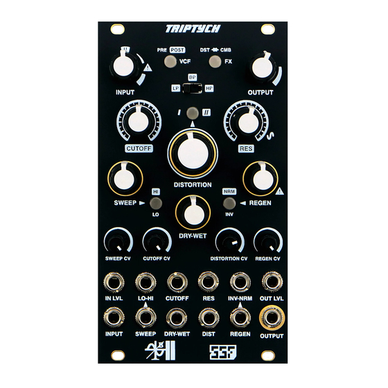
Page 3: Triptych Feature Map
VCF Type Select VCF Route Button DISTORTION/COMB Route Button Input Level Control Output Level Control VCF Resonance Control VCF Cuto Control Distortion Control and Mode Button Flange/Comb Clock Sweep and Clock Range Button Flange/Comb Regeneration and Feedback Type Button Flange/Comb DRY-WET Cross-fader Distortion and Regen CV Attenuators Sweep and Cuto CV Attenuators Output VCA CV Input... -
Page 4: Features Explained
FUNCTIONS INPUT VCA The INPUT jack, INPUT potentiometer, and IN LVL CV jack make up the Input VCA. Patch a signal into the INPUT to process the audio through the Triptych. Adjust the gain or attenuation via the INPUT control potentiometer. A decent amount of gain with soft saturation is available to overdrive the VCF, Distortion and FX sections, depending on your routing con guration. - Page 5 FUNCTIONS continued VOLTAGE CONTROLLED FLANGE-COMB The nal component of the Triptych and the most expressive and potentially destructive of the three. E ects range from fast delays to anging and comb ltering. This is a resonant e ect and can be very aggressive, especially when processed through the Distortion section.
-
Page 6: Signal Path Routing
SIGNAL PATH ROUTING SCHEMES PRE-FILTER ROUTING MODES: The following two schemes involve the Multi-Mode VCF section immediately following the Input VCA. In general, this con guration is suited for but not limited to input signals involving a higher order of harmonic content. - Page 7 SIGNAL PATH ROUTING SCHEMES cont.. POST-FILTER ROUTING MODES: The nal two schemes involve the Multi-Mode VCF section placed immediately before the Output VCA, after the Distortion and Flange/Comb sections. In general, these con gurations are suited for all signal types. Placing the VCF last in the chain allows for greater control over the frequency content and overall ability to ‘carve out’...
-
Page 8: Appendix
APPENDIX DISTORTION WAVEFORM EXAMPLES: TRIANGLE WAVE input shown with INPUT set @ U and increasing DISTORTION and INPUT levels TYPE I TYPE II... - Page 9 PATCH EXAMPLES COMING SOON...
Need help?
Do you have a question about the BII Electronics TRIPTYCH and is the answer not in the manual?
Questions and answers