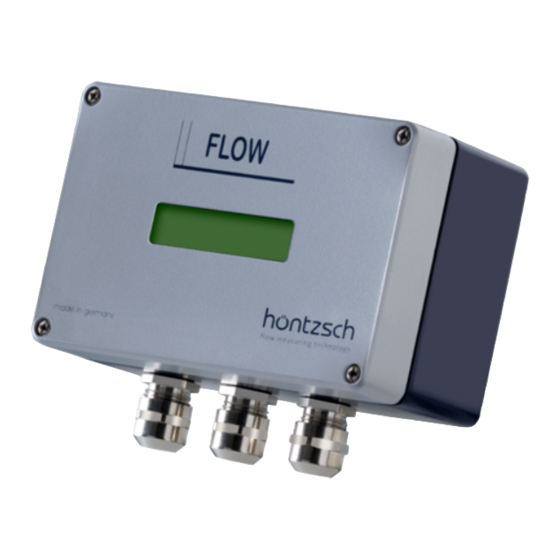
Hontzsch UFA Operating Instructions Manual
Hide thumbs
Also See for UFA:
- Operating instructions manual (15 pages) ,
- Operating instructions manual (17 pages)
Table of Contents
Advertisement
Quick Links
Operating Instructions
Transducers UFA and UVA in
AS102 housing
Vane wheel flow sensors FA
Höntzsch GmbH
P.O. Box 1324 D-71303 Waiblingen
Gottlieb-Daimler-Straße 37
D-71334 Waiblingen (Hegnach)
Tel: 07151/1716-0
Fax: 07151/58402
E-Mail info@hoentzsch.com
Internet www.hoentzsch.com
U328_UFAUVAextAS102_B_e_091103
Transducers UFA / UVA
in AS102 housing
Operating Instructions
www.hoentzsch.com
Vortex flow sensors VA
zertifiziert nach
ISO 9001 : 2000
certified quality
1/15
Advertisement
Table of Contents

Summary of Contents for Hontzsch UFA
- Page 1 Operating Instructions Transducers UFA and UVA in AS102 housing zertifiziert nach ISO 9001 : 2000 certified quality Transducers UFA / UVA in AS102 housing Operating Instructions Vane wheel flow sensors FA Vortex flow sensors VA Höntzsch GmbH P.O. Box 1324 D-71303 Waiblingen Gottlieb-Daimler-Straße 37...
-
Page 2: Table Of Contents
Operating Instructions Transducers UFA and UVA in AS102 housing Contents Safety Symbols Application according to Regulations Operating Safety Scope of Delivery Description, Type Plates Technical Specifications Conformity with Standards Storage Conditions Operating Conditions Compatibility Housing and Connectors Electrical Data Measurement Uncertainty... -
Page 3: Safety Symbols
Transducers UFA and UVA are instruments for measuring flow velocity and flow rate: UFA for use with vane wheel flow sensors FA or FAR and measuring tubes FA Di or FAR Di and UVA for use with vortex flow sensors VA40 and measuring tubes VA Di. These instruments are designed for industrial application. -
Page 4: Description, Type Plates
: RJ22 plug Technical Specifications Conformity with Standards Transducers UFA / UVA are manufactured according to the best available technology, are safe and reliable and comply with the relevant regulations, EU directives and standards. IEC 529 and EN 60 529... -
Page 5: Compatibility
(10 ... 17 V DC), power < 5 W The mains supply is electrically isolated from the UFA/UVA inputs and outputs. UFA input flow v/FA or v/FAR: for Höntzsch vane wheel flow sensors FA and FAR designed as probes (ZS, TS ..., ZSR, TSR ...) and as measuring tubes (FA Di, FAR Di ...). -
Page 6: Measurement Uncertainty
Operating Instructions Transducers UFA and UVA in AS102 housing UVA analog output: 4 ... 20 mA = 0 ... x m/s (or m³/h), terminal value x configurable / burden max. 400 Ohm, alternative: 0 ... 10 V = 0 ... x m/s (or m³/h), terminal value x configurable / impedance 1 kOhm Relay: (potential-free change-over contact), max. -
Page 7: Wiring Diagrams
Before connecting please check that the power supply is within the specification. Remove the housing cover of the UFA or UVA to reveal the type plate with all relevant information. With a supply voltage of 230 VAC please ensure that the non-insulated areas of terminals and connecting... -
Page 8: Sensor Input
Operating Instructions Transducers UFA and UVA in AS102 housing 6.2.3 Sensor input FA / FAR Sensor VA Sensor = shielding = shielding = FA signal 1 = VA signal = FA ground = VA ground V+ = FA supply (*opt.) -
Page 9: Rs232 Interface
Operating Instructions Transducers UFA and UVA in AS102 housing 6.2.6 RS232 Interface Fig. 1: PC connection with RJ22 plug with open cover The RS232 interface connection is below left next to the connecting terminals. The RJ22 plug of the PC connecting cable is plugged in to the socket (see Fig. 1). PC connection follows at a COM port or using an optional USB adapter. -
Page 10: Tips On Electromagnetic Compatibility (Emc)
Operating Instructions Transducers UFA and UVA in AS102 housing 6.3 Tips on Electromagnetic Compatibility (EMC) • all connecting cables are to be kept as short as possible • with cable routes longer than 30 m or with strong electromagnetic disturbance along the cable route... -
Page 11: Functional Description
AS102 housing Functional Description UFA transducers are designed for connecting to vane wheel probes FA and FAR (directional sensing) and vane wheel measuring tubes FA Di and FAR Di (directional sensing) for measuring flow velocity or flow ra- te of air/gases and water/liquids. -
Page 12: Settings
Operating Instructions Transducers UFA and UVA in AS102 housing Configuration (see Fig. 1) via 2 jumper wrap connectors ST1 and ST2 Display line 1: ST1 = m/s and ST2 = any: velocity in (N)m/s * ST1 = m³/h (lt/h) and ST2 = A: flow rate in (N)m³/h... -
Page 13: Operation
15 Calibration The UFA and UVA transducers have an excellent long-term stability. However, it makes sense to have the instruments calibrated at certain intervals. The period between two calibrations depends on the individual operational conditions and the tolerable measurement error. Therefore, as a precaution, shorter calibra- tion cycles should be chosen at the beginning. -
Page 14: Troubleshooting
6.3 17 Returns No special measures necessary for UFA and UVA transducers. When returning sensors, these should be cleaned thoroughly according to the instructions. A hazard warn- ing or declaration of no objection must be supplied for substances which have been in contact with the sensor or possibly infiltrated the cavities in the sensor. -
Page 15: Replacement Parts
Operating Instructions Transducers UFA and UVA in AS102 housing 19 Replacement Parts Fuse TR5 (2) is situated in the base behind the power supply connecting terminals and is easily accessible by loosening the screws (1) to remove the cover plate: for 230 V AC TR5-T 100 mA order no.

Need help?
Do you have a question about the UFA and is the answer not in the manual?
Questions and answers