Table of Contents
Advertisement
Available languages
Available languages
Quick Links
Advertisement
Chapters
Table of Contents

Related Manuals for Moretti iRoll iP 45

Summary of Contents for Moretti iRoll iP 45
- Page 1 Manuale di istruzioni Instructions manual Manual d’instructions Bedienungsanleitung iP 33 iP 45 Formatrice a caldo Pizza moulder Formeuse a pizza Pizzapressen Numeri di matricola / Serial numbers : Cod.73340930 Ver.: A4...
- Page 3 - m a i l : m a r k e t i n g @ m o r e t t i f o r n i . c o m Dichiarazione di conformità Noi, MORETTI FORNI SPA, Via A. Meucci, n. 4 – 61037 Mondolfo (Pesaro) - Italia, dichiariamo sotto nostra esclusiva responsabilità che il prodotto: Mod.
- Page 4 We declare under sole responsability that the products to which this declaration relates is in conformity with the following standards <> following the provisions of the directives<>.
-
Page 5: Table Of Contents
SOMMARIO CAPITOLO 1 INFORMAZIONI GENERALI................6 CAPITOLO 2 INSTALLAZIONE..................10 CAPITOLO 3 MESSA IN FUNZIONE ................12 CAPITOLO 4 USO ....................... 15 CAPITOLO 5 REGOLAZIONI ..................17 CAPITOLO 6 MANUTENZIONE ................... 18 CAPITOLO 7 DEMOLIZIONE DELLA MACCHINA ............19 CAPITOLO 8 SERVIZIO POST-VENDITA ..............20 Prefazione Questo manuale è... -
Page 6: Capitolo 1 Informazioni Generali
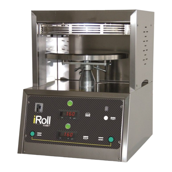
CAPITOLO 1 INFORMAZIONI GENERALI 1.1 Garanzia La durata della garanzia è di 2 anni a decorrere dalla data della fattura o ricevuta fiscale rilasciata all’atto dell’acquisto. Entro tale periodo verranno sostituiti o riparati gratuitamente e solo franco ns. stabilimento i particolari che per cause ben accertate presentino difetti di fabbricazione (sono esclusi i componenti elettrici e quelli soggetti ad usura). - Page 7 FIG. 1 iP 33 – iP45 1.3 Caratteristiche tecniche Modello Peso pasta Piatto inox Assorbimento Alimentazione Dimensioni Peso Volt iP 33 100 - 270 400/50/3 560 x 430 x 750 mm iP 45 100 - 500 400/50/3 670 x 550 x 860 mm 1.4 Zona occupata dall’operatore In normali condizioni operative e per lo sfruttamento ottimale delle potenzialità...
- Page 8 FIG. 2 mt 1 mt 2 1.5 Informazioni sulla rumorosità Il livello di pressione acustica ponderato A misurato su una identica macchina campione è risultato di valore costante ed inferiore a 70 dB (A). 1.6 Avvertenze per la sicurezza La macchina pur essendo conforme ai requisiti di sicurezza previsti dalle norme di riferimento, elettriche, meccaniche, igieniche, può...
- Page 9 1.7 Avvertenze per la sicurezza INFORMAZIONI Leggere attentamente queste istruzioni prima di utilizzare la macchina. ATTENZIONE Allo scopo di prevenire condizioni di pericolo e/o possibili ferimenti causati da: corrente elettrica, organi meccanici, incendio, o di natura igienica, devono essere osservate le seguenti avvertenze per la sicurezza: A - Mantenere in ordine il proprio posto di lavoro.
-
Page 10: Capitolo 2 Installazione
CAPITOLO 2 INSTALLAZIONE 2.1 Prescrizioni a carico dell'utente La macchina dev'essere installata in un luogo con le seguenti condizioni ambientali: · Essere asciutto (la macchina è costruita in modo da avere un livello di protezione IP21); · Fonti idriche e di calore adeguatamente distanti ·... - Page 11 Nota: Tutti i particolari relativi all'Imballo devono essere smaltiti secondo le vigenti leggi. 2.3 Collegamento elettrico FIG. 3 Il collegamento tipo Y della macchina alla rete elettrica viene effettuato tramite cavo di alimentazione, alla cui estremità va montata una spina normalizzata e polarizzata (la distinzione fra fase e neutro dev'essere inequivocabile).
-
Page 12: Capitolo 3 Messa In Funzione
CAPITOLO 3 MESSA IN FUNZIONE La macchina è dotata dei seguenti dispositivi di comando,di sicurezza e di segnalazione luminosa (FIG. 4). 3.1 Dispositivi di comando e segnalazione luminosa Sul pannello frontale: A- Termostato di regolazione temperatura disco superiore B- Termostato di regolazione temperatura disco inferiore A1/B1- Segnalatori elementi riscaldanti attivati C - Pulsanti di avviamento ciclo salita discesa disco inferiore D - Temporizzatore di sosta fase compressione... - Page 13 FIG. 4 D2-E1 FIG. 5 VALORE / C° ± 5% 1 = 56° 2 = 68° D-D2-E1 3 = 86° 4 = 104° 5 = 122° 6 = 140° 7 = 158° 8 = 176° 9 = 194° 10 = 210° iP 33-45 Manuale d’uso e manutenzione...
- Page 14 3.3 Verifica funzionale Dopo aver inserito la spina nella presa di alimentazione elettrica la macchina pronta per la verifica funzionale. ACCENSIONE Ruotare la manopola dell’interruttore E (FIG. 4; 5) in posizione 1, la macchina rimane in attesa. Programmare il temporizzatore D a 10 secondi, regolare le manopole A-B (FIG. 5) a 150° C. I segnalatori A1-B1-E1 risulteranno illuminati.
-
Page 15: Capitolo 4 Uso
CAPITOLO 4 USO Prima di iniziare ogni ciclo di lavoro accertarsi che la macchina sia perfettamente pulita, in paricolare le superfici di contatto dei dischi con la pasta. Qualora necessario procedere alla pulizia secondo le modalità 6.1. Allo scopo di ottimizzare la formatura della pasta nei primi cicli e all’occorrenza anche i quelli successivi, stendere un sottile velo d’olio sulle superfici di contatto dei dischi con la pasta. - Page 16 INFORMAZIONI Se durante la fase si rende necessario interrompere la salita del disco inferiore e riportarlo nella posizione di riposo, spingere verso l’alto la protezione G (FIG. 4). SPEGNIMENTO Ruotare la manopola dell’interruttore E in posizione 0 a conclusione della fase operativa. Alla fine di ogni utilizzo procedere alla pulizia secondo le modalità...
-
Page 17: Capitolo 5 Regolazioni
CAPITOLO 5 REGOLAZIONI Le regolazioni consigliate hanno carattere puramente indicativo in quanto per la presenza delle seguenti variabili: caratteristiche dell’impasto, grammatura, spessore e grandezza del disco, le regolazioni vanno definite sperimentalmente. 5.1 Regolazione dello spessore La macchina viene fornita con una regolazione di massima, (1 mm circa) idonea per la formatura di pizze di media grammatura. -
Page 18: Capitolo 6 Manutenzione
CAPITOLO 6 MANUTENZIONE INFORMAZIONI Prima di eseguire qualsiasi intervento di manutenzione, pulizia compresa, si deve staccare la spina dalla presa della rete di alimentazione e attendere il completo raffreddamento dei dischi. In caso di malfunzionamento o di guasto della macchina rivolgersi esclusivamente ai centri di assistenza autorizzati dal costruttore. -
Page 19: Capitolo 7 Demolizione Della Macchina
6.2 Possibili anomalie ANOMALIA CAUSA SOLUZIONE La macchina non si avvia · Mancanza di energia · Verificare: il contattore elettrica nella rete generale, la presa, la spina e il cavo di alimentazione · La manopola dell'interruttore generale è in posizione 0 Il disco inferiore si blocca ·... -
Page 20: Capitolo 8 Servizio Post-Vendita
CAPITOLO 8 POST-VENDITA 8.1 Parti di ricambio INDICAZIONE PER L'ORDINAZIONE DELLE PARTI DI RICAMBIO Per le ordinazioni delle parti di ricambio devono essere comunicate le seguenti indicazioni: · Tipo apparecchiatura · Numero di matricola · Denominazione del pezzo · Quantità occorrente iP 33-45 Manuale d’uso e manutenzione... - Page 21 SUMMARY CHAPTER 1 GENERAL INFORMATION ..............22 CHAPTER 2 INSTALLATION ..................26 CHAPTER 3 FUNCTIONING ..................28 CHAPTER 4 USAGE ....................31 CHAPTER 5 REGULATIONS ..................33 CHAPTER 6 MAINTENANCE ..................34 CHAPTER 7 DEMOLITION OF THE MACHINE ............35 CHAPTER 8 AFTER SALE SERVICE ................
-
Page 22: General Information
CHAPTER 1 GENERAL INFORMATION 1.2 Warranty The warranty starts from date of purchase. The date must be stamped on the guarantee on the date of purchase. Parts of the machine found to be a production defect except electrical components or parts worn out, will be changed and serviced free by us in our firm but only ex our factory within this period. - Page 23 PICT. 1 iP 33 – iP 45 1.4 Technical characteristics Model Dough weight Stainless steel plate Absorbed power Volt Dimensions Weight iP 33 100 - 270 400/50/3 560 x 430 x 750 mm iP 45 100 - 500 400/50/3 670 x 550 x 860 mm 1.7 Operating area In normal working conditions and to bave the best exploitation of the potentiality of the machine, the operator needs the area represented in PICT.
- Page 24 PICT. 2 mt 1 mt 2 1.8 Information regarding acoustic noises The acoustic pressure level considered A measured by an identical sample machine resulted of a constant value and lower than 70 dB CA). 1.9 General security indications Although the machine is built in conformity to the required security rules regarding electrical, mechanical and hygienic regulations it can be dangerous if: ·...
- Page 25 1.7 Security indications INFORMATION Carefully read the instructions before using the machine. WARNING To avoid dangerous conditions and/or possible injuries caused from: electric current, mechanical parts, fire or hygiene problems, you must follow the security indications step by step: A- Keep in order your working area. Disorder can cause dangerous accidents. B- Consider environmental conditions.
-
Page 26: Installation
CHAPTER 2 INSTALLATION 2.1 Instructions for the User The environmental conditions in which the machine must be installed must follow these characteristics: (The machine is made in such a way as to have an IP21 level of protection) · Be dry ·... - Page 27 Note: All packaging must be disposed of in a lawful way. 2.3 Electrical connection PICT. 3 The connection type Y of the machine to the power grid is made by the feeding cable, to whose end a normalized and polarized plug must be assembled (the distinction between phase and neutral must be unequivocal).
-
Page 28: Functioning
CHAPTER 3 FUNCTIONING The machine is provided with the following control, security devices and lights (PICT. 4). 3.1 Control devices and signal light devices On the frontal panel A- Thermostat to regulate temperature of the upper plate B- Thermostat to regulate temperature of the lower plate A1/B1- On of signal of the heating elements C- Start buttons up/down cycle of the lower plate D- Timer to regulate time of pressure... - Page 29 PICT. 4 D2-E1 PICT. 5 VALUE / C° ± 5% 1 = 56° 2 = 68° D-D2-E1 3 = 86° 4 = 104° 5 = 122° 6 = 140° 7 = 158° 8 = 176° 9 = 194° 10 = 210° iP 33-45 Operating manual...
- Page 30 3.3 Functional test After inserting the plug the machine is ready for use. IGNITION Rotate the knob of the switch E (PICT. 4-5) in position 1, the machine waits. Set the timer D at 10 seconds and regulate the knobs A-B (PICT. 5) at ISO° C. The devices A1-B1-E1 will be lighted. OPERATING Push the buttons C at the same time to activate the up/down cycle of the lower plate.
-
Page 31: Usage
CHAPTER 4 USAGE Before starting work make sure that the machine is perfectly clean, in particular surfaces of pan and spiraI that have contact with dough. If necessary clean them following indications at 6.1. To get the best result and shape of the dough before using the machine, wipe a thin layer of oil on the disk surfaces that are in contact with the dough. - Page 32 INFORMATION While the machine is operating In order to stop the rise of the lower plate it is sufficient to touch upwards the protection G. (PICT. 4) TO TURN OFF Turn the knob of the switch E to position 0 for the conclusion of the operative phase. When work cycle is completed, proceed with cleaning of the machine following the indications at 6.1.
-
Page 33: Regulations
CHAPTER 5 REGULATIONS Regulating the machine can only be recommended as there are different characteristics of: the dough, the weight, the thickness, the size and the shape of the disk. Therefore the correct regulating of the machine must be made by experimenting. 5.1 How to regulate the thickness The machine is provided with a medium (about 1 mm) size regulation for the shapes of pizza. -
Page 34: Maintenance
CAPTHER 6 MAINTENANCE INFORMATION Before effecting any kind of maintenance or cleaning you must take out the plug and wail for complete cooling of the disks. In any case of malfunctioning or damage of the machine you must apply for authorized assistance from the manufacturer (see Chapter 8). 6.1 Cleaning The cleaning must be done every time the machine has been used following all the rules to prevent malfunctioning of the machine and for hygienic purposes. -
Page 35: Demolition Of The Machine
6.2 Possible anomalies ANOMALY CAUSE SOLUTION The machines does · Electric energy is missing · Check the general switch, not start in the net the plug, the tap and the feeding cable · The knob of the generaI · Rotate the knob in position 1 switch is in position 0 The lower plate stops ·... -
Page 36: After Sale Service
CHAPTER 8 AFTER SALE SERVICE 8.1 Spare parts INSTRUCTIONS FOR ORDERING SPARE PARTS Orders for spare parts must contain the following information: · Oven type · Oven serial number · Name of part · Number required iP 33-45 Operating manual... - Page 37 SOMMAIRE CHAPITRE 1 INFORMATIONS GÉNÉRALES ............... 38 CHAPITRE 2 INSTALLATION ..................42 CHAPITRE 3 MISE EN MARCHE ................44 CHAPITRE 4 UTILISATION..................47 CHAPITRE 5 REGLAGES ..................49 CHAPITRE 6 ENTRETIEN ..................50 CHAPITRE 7 DEMOLITION DE LA MACHINE ............. 51 CHAPITRE 8 SERVICE APRÈS VENTE ..............
-
Page 38: Chapitre 1 Informations Générales
CHAPITRE 1 INFORMATIONS GÈNERALES 1.3 Garantie La garantie est valable à partir de la date de reception du reçu fiscal delivré au moment de l'achat. Pendant celte periode les details qui pour des raisons bien évaluées et sans équivoque s'avèrent de fabrication défectueuse, sauf les parties élèctriques et celIes éxposées l'usure, seront à... - Page 39 FIG. 1 iP 33 – iP 45 1.5 Caractéristiques techniques Modèle Poids de la pâte Disque en acier inoxydable Pouvoir absorbé Volt Dimensions Poids iP 33 100 - 270 400/50/3 560 x 430 x 750 mm iP 45 100 - 500 400/50/3 670 x 550 x 860 mm 1.10...
- Page 40 FIG. 2 mt 1 mt 2 1.11 Informations sur le bruit Le niveau de pression acoustique ponderé A, mesuré sur une identique machine échantillon, résulte de valeur constante et inferieure à 70 dB (A). 1.12 Informations generaux des securité Meme si la machine est conforme aux règles de securité prévues par les normes de reference éléctrique, mecanique, hygienique, il y a danger si: ·...
- Page 41 1.7 Indications des securité INFORMATIONS Lire attentivement ces instructions avant d'employer la machine. ATTENTION Dans le but de prévenir les conditions de danger et/ou éventuelles blessures provoquées par: le courant éléctrique, parties mecaniques, incendie, ou d'origine hygiénique, les normes de securité suivantes doivent etre obsèrvées. A- Le poste de travail doit etre maintenu en ordre.
-
Page 42: Chapitre 2 Installation
CHAPITRE 2 INSTALLATION 2.1 Préscriptions pour l'usager Les conditions du milieu ambiant ou l'on piace la machine ont les caract eristiques suivantes: (La machine a étée costruite en facon d'avoir un livel de proctection IP21) · Etre sec · Sources hydriques et de chaleurs suffisamment distantes ·... - Page 43 Note: Tous les détails relatifs à l'emballage doivent etre éxécutés selon les lois en vigueur. 2.3 Branchement électrique FIG. 3 Le branchement type Y de la machine au secteur électrique sera effectué par un cable d'alimentation sur lequel il est indispensable de brancher à...
-
Page 44: Chapitre 3 Mise En Marche
CHAPITRE 3 MISE EN MARCHE La machine est composée des suivants dispositifs de commande, de sieurité et de signalisation lumineuse (FIG. 4). 3.1 Dispositifs de commande et signalisation lumineuse Sur le panneau frontal A - Thermostat de régulation de température du disque supérieur B - Thermostat de régulation de température du disque inférieur A1/ B1 - Signalisation éléments chauffants activés C - Boutons poussoir de mise en route du cycle montée descente du disque inféfieur... - Page 45 FIG. 4 D2-E1 FIG. 5 VALEUR / C° ± 5% 1 = 56° 2 = 68° D-D2-E1 3 = 86° 4 = 104° 5 = 122° 6 = 140° 7 = 158° 8 = 176° 9 = 194° 10 = 210° iP 33-45 Operer manuel...
- Page 46 3.3 Verification fonctionnelle Après avoir inseré la prise dans la prise d'alimentation éléctrique, la machine est prète pour etre verifié. MISE EN SERVICE Tourner la poignée de l'interrupteur E (FIG. 4;5) en position 1, la machine reste en état d'attente. Programmer la temporisation D à...
-
Page 47: Chapitre 4 Utilisation
CHAPITRE 4 UTILISATION Avant de commencer chaque cycle de travail, verifier que la machine soit parfaitement nettoyée en particulier Ies surfaces de contact avec la pate. Dans le cas ou il est necessaire proceder au nettoyage suivant Ies modalités 6.1. Dans le but d'optimiser le format de la pate dans Ies primiers cicles et dans Ics cicles suivants étendre une fine couche d'huile sur Ies surfaces de contact des disques avec la pate. - Page 48 INFORMATIONS Pendant la phase opérative, s'il est nécessaire d'interrompre la montée du disque inférieur et de le reporter dans la position de repos, pousser vers le haut la protection G. (FIG. 4) EXTINCTION Tourner la poignée de l'interrupteur E à la position 0 pour conclure la phase operationelle. Le cycle de travail terminé, proceder au nettoyage de la machine suivant Ies modalités 6.1.
-
Page 49: Chapitre 5 Reglages
CHAPITRE 5 REGLAGES Les réglages conseillés ont un caractère purement indicatif, à cause des variantes suivantes: caracteristiques du pétrissage, grammage, épaisseur et grandeur du dusque, Ies réglages sont definis experimentalement. 5.1 Réglage de l'épaisseur La machine est fournie avec un réglage maximum (1 mm) propre au formage de pizza dont le grammage est moyen. -
Page 50: Chapitre 6 Entretien
CHAPITRE 6 ENTRETIEN INFORMATIONS Avant d'éxécuter n'importe quelle opération d'entretien, y compris le nettoyage, il faut debrancher la prise du panneau d'alimentation et attendre le refroidissem ent complet des disques, En cas de defaillance ou de panne de la machine s'adresser uniquement aux centres d'assistance autorisés par le fabricant (voir Chapitre 8). -
Page 51: Chapitre 7 Demolition De La Machine
6.2 Anomalies possibles ANOMALIE CAUSE SOLUTION La machine ne se met · Manque d'énergie électrique · Vérifier le contacteur pas en marche sur le secteur général, la fiche, la prise et Ie cable d'alimentation · La poigne de l'interrupteur · Tourner la poignée général est en position 0 en position 1 Le disque inférieur... -
Page 52: Chapitre 8 Service Après Vente
CHAPITRE 8 SÈRVICE APRÈS VENTE 8.1 Piéces de recange INSTRUCTION POUR COMMANDER LES PIECES DE RECHANGE Les commandes pour les pièces de rechange doivent contenir les indications suivantes: · Type de four · Numéro de série de la planche · Numéro de référence de la pièce ·... - Page 53 ZUSAMMENFASSUNG KAPITEL 1 ALLGEMEINE INFORMATIONEN............... 54 KAPITEL 2 INSTALLATION ..................58 KAPITEL 3 IN BETRIEBNAHME.................. 60 KAPITEL 4 GEBRAUCH..................... 63 KAPITEL 5 REGULIERUNGEN ..................65 KAPITEL 6 WARTUNG ....................66 KAPITEL 7 VERSCHROTTUNG DER MASCHINE............67 KAPITEL 8 SERVICE NACH VERKAUF................ 68 Einleitung Dieses handbuch wurde vom hersteller geschrieben, um alle nutzlichen informationen fur eine korrekte installation, einen gebrauch und eine wartung der maschine zu geben, mit extremer vorsicht, gefahren fur den operator wahrend der anwendung zu vermeiden.
-
Page 54: Kapitel 1 Allgemeine Informationen
KAPITEL 1 ALLGEMEINE INFORMATIONEN 1.4 Garantie Die Garantie beginnt nach Erhalt der Stenerquittung bei Erwerb. Innerhalb dieses Zeitraumes werden kostenfrei und nur ab unserem Werk die Teile repariert oder ersetzt, die zweifeIsfrei auf Fabrikationsfehler zurückzuführen sind, ausgenommen sind elektrische Bau und Verschleissteile. Von der Garantie sind Versand und Arbeits kosten ausgenommen. - Page 55 BILD 1 iP 33 – iP 45 1.6 Technische Eigenschaften Model Gewicht teig Edelstahl-Scheibe Kraft einsaugen Volt Umfang Gewicht iP 33 100 - 270 400/50/3 560 x 430 x 750 mm iP 45 100 - 500 400/50/3 670 x 550 x 860 mm 1.13 Arbeitsbereich Unter normalen Arbeitsbedingungen und zur optimalen Nutzung der Maschinenkraft benötigt der...
- Page 56 BILD 2 mt 1 mt 2 1.14 Informationen zur Lautstärke Die Höhe des Schalldruckes A, an einer gleichen Probemaschine gemcssen, hat einen konstanten Wert von unter 70 dB (A). 1.15 Anweisungen fuer die Sicherheit Die Maschine, obwohl sie den Sicherheitsvorschriften entspricht in Bezug auf Normen im Elektro, Mechanik und Hygienebereich, kann Gefahren bergen, falls: ·...
- Page 57 1.7 Sicherheitsanweisungen WICHTIG Vor in Betriebnahme aufmerksam die Gebrauchseinweisung lesen. ACHTUNG Um eventuellen Gefahrenquellen vorzubeugen, dìe auf Strom, mech. Teile, Feuer oder hygienische Natur zurückzuführen sind, müssen folgende Sicherheitsanweisungen eingehalten werden. A- Den Arbeitsplatz in Ordnung halten. Unordnung Feuergefahr birgt. B- Die Umgebungsbcdingungen beachten.
-
Page 58: Kapitel 2 Installation
KAPITEL 2 INSTALLATION 2.1 Vorschriften für den Benutzer Die Bedingungen des Ortes, wo die Maschine aufgestellt wird, solite folgende Eigensehaften besitzen: (Die Maschine ist so gebaut, dass sie einen IP21 Schutzstand hat) · Trocken · Wasser und Hitzequellen in entsprechender Entfernung ·... - Page 59 Anmerkung: Alle relativen Einzelteile müssen gesetzmässig lackiert sein. 2.3 Elektroanschluss BILD 3 Die Maschine wird durch Zuleitungskabel an das elektrische Netz angeschlossen (Anschluß Typ Y), an welchem Ende ein abgesicherter und polarisierter Stecker angebracht werden muss. 2.4 Åquipotentialschaltung Die Maschine muss innerhalb von einem Aequipotentialsystem eingeschlossen werden.
-
Page 60: Kapitel 3 In Betriebnahme
KAPITEL 3 IN BETRIEBNAHME Die Maschine ist mit folgenden Steürwerk und Sicherheitslampe ausgerüstet (BILD 4). 3.1 Bedienungen und Lichtanzeiger An der Frontplatte: A - Wärmeregler für die obere Scheibe B - Wärmeregler für die untere Scheibe A1/B1- Funktìonsanzeiger der Heizkomponenten C - AnlaufSchalter (2) für das An und Absteigen der unteren Scheibe D - Zeitregler für das Halten bei der Kompressionsphase D1 - Zeitauswahlsknopf... - Page 61 BILD 4 D2-E1 BILD 5 WERT / C° ± 5% 1 = 56° 2 = 68° D-D2-E1 3 = 86° 4 = 104° 5 = 122° 6 = 140° 7 = 158° 8 = 176° 9 = 194° 10 = 210° iP 33-45 Handbuch des gebrauches und der wartung Auflage...
- Page 62 3.3 Funktionspriifung Nachdem der Stecker in die Steckdose gesteckt ist, ist die Maschine Funktionsbereit. EINSCHALTUNG Wähler des Schalters E (BILD 4-5) auf 1 drehen: somit wird die Maschine bereit gemacht. Zeitregler D auf 10 Sekunden programmieren; Wähler A-B (BILD 5) auf 150° C einstellen: die Lichtanzeiger A1-B1-E1 leuchten auf.
-
Page 63: Kapitel 4 Gebrauch
KAPITEL 4 GEBRAUCH Vor Beginn eincs Arbeitszyclus sicherstellen, dass die Maschine und besonders die Obcrflächen mit Kontakt des Teiges richtig gesäubert sind. Sollte es nötig sein, nach den Modalitäten 6.1 vorgehen. Um die Teigformung zu verbessern, bei ersten Gebräuche, und wenn nötig auch später, eine dünne Schicht Öl auf die Oberflächen der Seheiben, die im Kontakt mit dem Teig sind, auftragen. - Page 64 WICHTIG Falls es während des Betriebs unvermeidbar ist, das Ansteigen der unteren Scheibe zu unterbrechen, um sie in die Ruhe Position wieder zu bringen, muss man den Handschutz G nach oben schieben (BILD 4). AUSSCHALTEN Am Ende der Arbeitsphase den Handgriff des Schallers E auf 0 stellen. Nach Absehluss des Arbeitszyklus dir Reinigung der Maschine den Modalitäten 6.1 entspreehend vornehmen.
-
Page 65: Kapitel 5 Regulierungen
KAPITEL 5 REGULIERUNGEN Die empfohlenen Regulierungen haben nur hinweisenden Charakter, da sie für folgende Variablen ausprobiert werden müssen: Teigbeschaffenheit, Gewicht, Stärke und Grösse der Scheibe. 5.1 Regulierung der Telgstarke Die Masehine wird mit einer Stärkenregulierung (1 mm zirka), die geeignet ist zum Formen von Pizzen mittleren Gewichtes. -
Page 66: Kapitel 6 Wartung
KAPITEL 6 WARTUNG WICHTIG Vor jeglichen Wartungsarbeiten, Reinigung eingenommen, den Stecker ziehen und das komplette Abkühlen der Scheiben abwarten. Für den Fall, daß die Maschine schlecht oder gar nicht funktioniert, sollte sich ausschliesslich an den Hersteller gewandt werden (Kap. 8). 6.1 Reinigung In Anbetracht der Hyglenevorschriften und dem allgemeinen Funktionieren der Maschine muss die Reinigung nach jedem Gebrauch vorgenommen werden. -
Page 67: Kapitel 7 Verschrottung Der Maschine
6.2 Mögliche Fehler FEHLER URSACHE BESELTIGUNG Maschine läuft nicht an · Stromausfall · Hauptschalter, Stecker, Steckdose und Speisekabel überprüfen · Wähler am Hauptschalter · Wahler auf 1 drehen ist auf 0 Untere Scheibe · Fremdkörper zwischen · Handschutz G nach blockiert wahrend den Scheiben oben schieben... -
Page 68: Kapitel 8 Service Nach Verkauf
KAPITEL 8 SERVICE NACH VERKAUF 8.1 Ersatzteile ANGABEN, DIE BEI DER BESTELLUNG VON ERSATZTEILEN NOTWENDIG SIND Bei der Bestellung von Ersatzteilen sind folgende Angaben erforderlich: · Gerättyp · Seriennummer · Bezeichnung des Teiles · Benötigte Menge iP 33-45 Handbuch des gebrauches und der wartung Auflage... - Page 69 iP 33-45 Handbuch des gebrauches und der wartung Auflage...
- Page 70 73301700 Revisione 00 Mod. iP 33-45...
- Page 71 Denominazione Designation Denomination Bezeichnung Piatto inox Stainless steel flat Plat inox Inox-stahlplatte Resistenza Resistance Resistance Widerstand Disco ferro Iron disk Disque ferre Eisenscheibe Disco isolcart Isolcart disk Disque isolcar Isolierscheibe Disco inox Stainless steel disk Disque inox Inox-stahlscheibe Distanziatore Spacer Distancer Abstandhalter Ghiera tubo...
- Page 72 Denominazione Designation Denomination Bezeichnung Scheda temporizzatore Timer card Fiche temporisateur Schaltuhrkarte Pannello comandi Control panel Panneau commande Schalttafel Scocca inferiore Lower chasis Coque inferieur Unterbau Pressacavo Cable tackle Presse j'arrache Kabelpresse Colonna destra Right column Colonne droit Stutze rechts Colonna sinistra Left column Colonne gauche Stutze links...
- Page 73 74800530 Revisione 00 MOD. iP 33 - 45...
- Page 74 74800530 Revisione 00 MOD. iP 33 - 45...
- Page 75 74800530 Revisione 00 MOD. iP 33 - 45...
Need help?
Do you have a question about the iRoll iP 45 and is the answer not in the manual?
Questions and answers