Table of Contents
Advertisement
Quick Links
Product Specification / User Manual
Load Amplifier Cassette
Instructions for Use / Manual
Load Amplifier Cassette
TRsystems GmbH
Freiburgerstraße 3
75179 Pforzheim
Germany
Tel.: 07231 / 3152-0
Fax: 07231 / 3152-99
email:
unidor@trsystems.de
Web:
http://www.trsystems.de
This user manual is kept up to date. As the TRsystems GmbH/ UNIDOR products are subject
to continual development, technical modifications might lead to temporary deviations between
the device design and the user manual. Please note that TRsystems GmbH is not liable for
damages caused as a result of these deviations.
© Copyright 2010 TRsystems GmbH , Systembereich Unidor
LVCpro-S
LVCpro-S
LVCpro-SV13_E.doc
Version 1.3 /08.11.10
Page 1 of 20
Advertisement
Table of Contents

Subscribe to Our Youtube Channel
Summary of Contents for unidor TRsystems LVCpro-S
- Page 1 Product Specification / User Manual Load Amplifier Cassette LVCpro-S Instructions for Use / Manual Load Amplifier Cassette LVCpro-S TRsystems GmbH Freiburgerstraße 3 75179 Pforzheim Germany Tel.: 07231 / 3152-0 Fax: 07231 / 3152-99 email: unidor@trsystems.de Web: http://www.trsystems.de This user manual is kept up to date. As the TRsystems GmbH/ UNIDOR products are subject to continual development, technical modifications might lead to temporary deviations between the device design and the user manual.
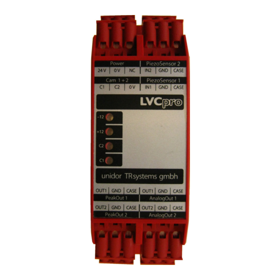
- Page 2 Product Specification / User Manual Load Amplifier Cassette LVCpro-S View of LVCpro-S Advantages Functionality Easy installation and wiring The load amplifier cassette enables a cost-efficient multichannel 24VDC supply voltage measurement of the press force by using piezo sensors, at even 2 measuring channels quasi-static processing.
-
Page 3: Table Of Contents
Amplification Factors Setting for DIP-Switches or Filters SW1 Commissioning of the LVCpro-S Ordering Data LVCpro-S Mechanical Dimensions LVCpro-S Opening of the Enclosure LVCpro-S General Information © Copyright 2010 TRsystems GmbH , Systembereich Unidor LVCpro-SV13_E.doc Version 1.3 /08.11.10 Page 3 of 20... -
Page 4: Safety Guidelines And Regulations
TRsystems GmbH is not liable for damages caused as a result of these deviations. Due Diligence of the Operator The LVCpro-S was designed and constructed followinga risk analysis and upon careful selection of the relevant standards to be complied with, as well as other technical specifications. - Page 5 Product Specification / User Manual Load Amplifier Cassette LVCpro-S Furthermore the operator is responsible for ensuring that... this personnel is regularly trained in all relevant matters of occupational safety • and environmental protection and knows the the contents of the user manual and especially the safety regulations therein.
- Page 6 Product Specification / User Manual Load Amplifier Cassette LVCpro-S Guarantee and liability will also be void if defects of the device are not • immediately notified to the supplier and appropriate measures for the damage control were implemented to late or not at all. Spare parts must correspond to...
- Page 7 Product Specification / User Manual Load Amplifier Cassette LVCpro-S General Fault Clearance Measures / Shielding The use of electronic sensor active systems in modern equipment requires a • consistent and correctly implemented fault clearance and wiring concept. The compliance with these requirements is important to ensure the proper function of a device with electronic measuring systems.
-
Page 8: Technical Specification
Product Specification / User Manual Load Amplifier Cassette LVCpro-S 2. Technical Specification Power Supply Input voltage: 10-32VDC / 24VDC nom. Input current: 90mA Amplifier Input resistance: / Ohm Output resistance: / Ohm Measuring Window Input voltage: 18-32VDC Input / Cams Input current: ca. -
Page 9: Terminal Assignment
Product Specification / User Manual Load Amplifier Cassette LVCpro-S 4. Terminal Assignment upper connectors Connector Function Power 24VDC 0VDC not connected CAM 1+2 Cams 1/Meas. Channel 1 Cams 2/Meas. Channel 2 0VDC PiezoSensor 2 Input Signal Sensor 2 Analogous-Mass CASE... -
Page 10: Connector Coding
Product Specification / User Manual Load Amplifier Cassette LVCpro-S 5. Connector Coding Power CAM 1+2 PiezoSensor 1 PeakOut 1 + 2 PiezoSensor 2 AnalogOut1 + 2 © Copyright 2010 TRsystems GmbH , Systembereich Unidor LVCpro-SV13_E.doc Version 1.3 /08.11.10 Page 10 of... -
Page 11: Connection Of The Piezo Sensors
Product Specification / User Manual Load Amplifier Cassette LVCpro-S 6. Connection of the Piezo Sensors Sensor JZT127/S with black connection cable for rack mounting Terminal assignment for pressure load Sensors Connector LVCpro-S Core Colour black Press Force Sensor PiezoSensor 1 Shield CASE... -
Page 12: Setting Of The Code Switches
Product Specification / User Manual Load Amplifier Cassette LVCpro-S 7. Setting of the Code-Switches The adjustment of the analogous inputs and outputs will be implemented through hexadecimal code and DIP-switches. The adjustments will be implemented separately for each channel. Channel / Sensor... -
Page 13: Amplification Factors
Product Specification / User Manual Load Amplifier Cassette LVCpro-S P302 SW401 SW402 P402 P202 SW202 SW201 P102 7. Amplification Factors Rough Adjustment Fine Adjustment Capacitive Capacity Amplification Amplification amplification (nF) Adjustment factor Code-switch Code-switch (times) SW201, SW401 SW202, SW402 71.8 11.12... -
Page 14: Setting For Dip-Switches Or Filters Sw1
Product Specification / User Manual Load Amplifier Cassette LVCpro-S * not permitted code-switch adjustments Measuring W ind ow (Cams) SW 201 SW 401 SW 202 SW 204 P102 P302 Pos. Input Sensor Neg. Filter Amplifier P202 Charge Amplifier P402 Mass Shield 8. -
Page 15: Commissioning Of The Lvcpro-S
F-limit = 1KHz F-limit = 355Hz (47nF II 33nF) (8=ON,7=OFF) 9. Commissioning of the LVCpro-S Wiring of the piezo sensors. Wire the measuring window and the outputs according to the PIN-assignment. Apply supply voltage (it is important to use the correct polarity!) Alignment (calibration) of the amplifiers with the piezo sensors used acc. -
Page 16: Ordering Data Lvcpro-S
10V). We recommend a final adjustment of 7V output voltage for maximum load to still enable an assessment in case of an overload. If replacing the load amplifier cassette LVCpro-S it is important to maintain the same adjustment of the code-switches, otherwise there is the risk of overload (falsification... -
Page 17: Mechanical Dimensions Lvcpro-S
Product Specification / User Manual Load Amplifier Cassette LVCpro-S additional cable length available on request • Mechanical Dimensions of the LVCpro-S © Copyright 2010 TRsystems GmbH , Systembereich Unidor LVCpro-SV13_E.doc Version 1.3 /08.11.10 Page 17 of... -
Page 18: Opening Of The Enclosure Lvcpro-S
Product Specification / User Manual Load Amplifier Cassette LVCpro-S Opening the LVCpro-S Enclosure 1. Use a screwdriver to push the splint in the opening tab down, located underneath the connector plugs of Power, PiezzoSensor2 and underneath PeakOut2 and AnalogOut2. 2. Using the screwdriver, push the... -
Page 19: General Information
3. …and push it backwards at the same time. Now repeat these steps for all 4 tabs to remove the entire enclosure lid. 4. You can now open the LVCpro-S and the code-switches for the adjustment and/or calibration of the press force are accessible. - Page 20 Product Specification / User Manual Load Amplifier Cassette LVCpro-S EN 55022 Radio Radiation VDE 0100, VDE 0113, EN 60204 Issued by: TRsystems GmbH , System Division Unidor Date: 26 May 2010 Place: Pforzheim, Germany © Copyright 2010 TRsystems GmbH , Systembereich Unidor LVCpro-SV13_E.doc...
Need help?
Do you have a question about the LVCpro-S and is the answer not in the manual?
Questions and answers