Advertisement
Quick Links
The Future of Analog IC Technology
DESCRIPTION
The MP5075 provides up to 2.4A of load
protection over a 3V to 5.5V voltage range with
a small R
in a space-saving package. The
DS(ON)
MP5075 is a very high-efficiency and space-
saving solution for notebooks, tablets, and other
portable and battery-operated applications.
With a fixed soft-start function, the MP5075 can
prevent inrush current during circuit start-up.
The MP5075 also provides output discharge
functions, over-current protection (OCP), and
thermal shutdown features.
The max load at the output (source) is current-
limited. This is accomplished by utilizing sense
FET topology.
An internal charge pump drives the gate of the
power device, allowing for a very low on-
resistance DMOS power FET of just 38mΩ.
The MP5075 is available in a space-saving
SOT563(1.6mmx1.6mm)package.
ELECTRICAL SPECIFICATIONS
Parameter
Symbol
Continuous Operating
Input Voltage
Output Voltage
Output Current
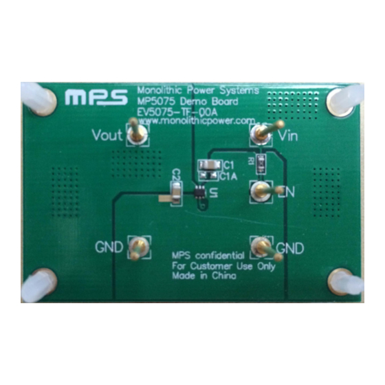
EV5075-TF-00A EVALUATION BOARD
(L × W × H) 51.0mm × 33.0mm × 3mm
Board Number
EV5075-TF-00A
EV5075-TF-00A Rev. 1.0
2/22/2017
MPS Proprietary Information. Patent Protected. Unauthorized Photocopy and Duplication Prohibited.
Value
Units
V
3-5.5
V
IN
V
3-5.5
V
Out
Iout
2.4
A
MPS IC Number
MP5075GTF
www.MonolithicPower.com
© 2017 MPS. All Rights Reserved.
EV5075-TF-00A
Low R
FEATURES
Integrated 38mΩLow R
Wide VIN Range from 3V to 5.5V
<5µA Shutdown Current
Typical 3A Current Limit
Output Discharge Function
Internal Fixed 450μs Soft-Start Time
<200ns
Short-CircuitProtection
Time
Thermal Protection
Available in a SOT563 (1.6mmx1.6mm)
Package
APPLICATIONS
Notebook and Tablet Computers
Portable Devices
Solid-State Drives
Handheld Devices
USB Power Distribution
USB Dongles
All MPS parts are lead-free, halogen free, and adhere to the RoHS directive. For
MPS green status, please visit MPS website under Quality Assurance. "MPS"
and "The Future of Analog IC Technology" are Registered Trademarks of
Monolithic Power Systems, Inc.
5.5V,2.4A
Load Switch
DS(ON)
MOSFETs
DS(ON)
Response
1
Advertisement

Related Manuals for MPS EV5075-TF-00A

Summary of Contents for MPS EV5075-TF-00A
- Page 1 USB Dongles The MP5075 is available in a space-saving SOT563(1.6mmx1.6mm)package. All MPS parts are lead-free, halogen free, and adhere to the RoHS directive. For MPS green status, please visit MPS website under Quality Assurance. “MPS” ELECTRICAL SPECIFICATIONS and “The Future of Analog IC Technology” are Registered Trademarks of Monolithic Power Systems, Inc.
-
Page 2: Evaluation Board Schematic
Ceramic Cap, X5R, 16V 0805 Murata GRM21BR61C106KE15L 0805 10KΩ Film Res, 1% 0603 ROYAL RL0603FR-0710KL Load Switch SOT563 MP5075GTF EV5075-TF-00A Rev. 1.0 www.MonolithicPower.com 2/22/2017 MPS Proprietary Information. Patent Protected. Unauthorized Photocopy and Duplication Prohibited. © 2017 MPS. All Rights Reserved. - Page 3 EVB TEST RESULTS Performance waveforms are tested on the evaluation board. = 5V, T = 25°C, unless otherwise noted. EV5075-TF-00A Rev. 1.0 www.MonolithicPower.com 2/22/2017 MPS Proprietary Information. Patent Protected. Unauthorized Photocopy and Duplication Prohibited. © 2017 MPS. All Rights Reserved.
- Page 4 EVB TEST RESULTS (continued) Performance waveforms are tested on the evaluation board. = 5V, T = 25°C, unless otherwise noted. EV5075-TF-00A Rev. 1.0 www.MonolithicPower.com 2/22/2017 MPS Proprietary Information. Patent Protected. Unauthorized Photocopy and Duplication Prohibited. © 2017 MPS. All Rights Reserved.
- Page 5 EVB TEST RESULTS (continued) Performance waveforms are tested on the evaluation board. = 5V, T = 25°C, unless otherwise noted. EV5075-TF-00A Rev. 1.0 www.MonolithicPower.com 2/22/2017 MPS Proprietary Information. Patent Protected. Unauthorized Photocopy and Duplication Prohibited. © 2017 MPS. All Rights Reserved.
-
Page 6: Printed Circuit Board Layout
E V5075-TF – 00A 5.5V, 2.4A LOW R LOAD SWITCH DS(ON) PRINTED CIRCUIT BOARD LAYOUT Figure 1—Top Silk Layer Figure 2—Top Layer Figure 2—Bottom Layer EV5075-TF-00A Rev. 1.0 www.MonolithicPower.com 2/22/2017 MPS Proprietary Information. Patent Protected. Unauthorized Photocopy and Duplication Prohibited. © 2017 MPS. All Rights Reserved. - Page 7 NOTICE: The information in this document is subject to change without notice. Users should warrant and guarantee that third party Intellectual Property rights are not infringed upon when integrating MPS products into any application. MPS will not assume any legal responsibility for any said applications.
Need help?
Do you have a question about the EV5075-TF-00A and is the answer not in the manual?
Questions and answers