Advertisement
Available languages
Available languages
Quick Links
OPERATING INSTRUCTIONS
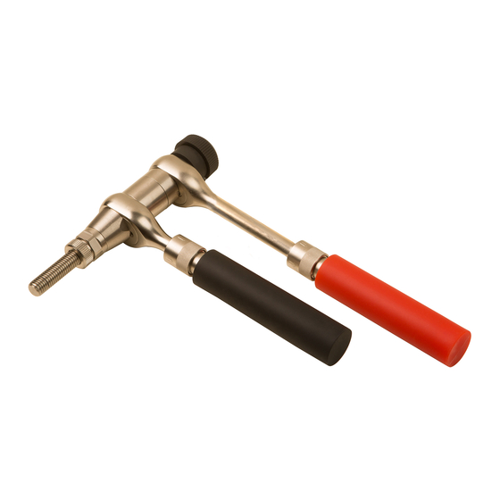
HAND TOOL FOR BLIND RIVET NUT M5-M12
AS N-12-R
1
3
4
5
6
7
8
9
2
TECHNICAL INFORMATION
Capacity:
Blind rivet nuts M5–M6–M8–M10 –M12
Material:
Aluminium, Steel and Stainless Steel
Size:
210 (L) x 180 (H) x 40 (P) mm
Weight:
1,82 kg
DESCRIPTION OF THE TOOL
1. Tool body
2. Front and back lever
3. Turning knob
4. Mandrel M12
5. Anvil M12
6. Counter lock nut
7. Stroke indicator
8. Ratchet switch
9. Lever extension system
Read the manua
l
INSTRUCTIONS
The hand tool will be standard equipped with the M12 anvil and
M12 mandrel. The other components will be stored separate in the
carton box.
FIRST USE:
Make sure before using the tool that the anvil and mandrel are
suitable for the thread of the insert to be used. Otherwise change
to a different size.
CHANGE TO A DIFFERENT SIZE:
A
Unscrew the anvil (5) and the lock nut (6). Use the two spanners
in the carton box to unscrew the mandrel (4). Please note that the
mandrels have
left-handed
thread. To unscrew turn the mandrel
clockwise. Replace it by choosing the correct size from the spare
parts in the carton box and turn counter clockwise to fasten.
8
7
5
2
7
3
8
8
2
9
B
ANVIL ADJUSTMENT:
After changing to a different size at A, it is necessary to adjust
the anvil (5) and its counter lock nut (6). Put the tool in its
starting position by pushing the ratchet switch (8) to the left
6
and turn the back lever (2) counterclock wise until the stroke
indicator (7) is invisible. The tool body is now in starting
position. The protrusion of the mandrel out of the anvil must
be as long as the whole rivet nut. Unscrewing the counter lock
nut (6) to adjust the anvil (5) by turning left or right, to
increase or decrease the length. After the correct length is
applied, screw the counter lock nut until it is tight.
C
SETTING A THREADED INSERT:
Put the tool in start position by pushing the ratchet switch
(8) to the left and turn the back lever (2) counterclock wise
until the stroke indicator is invisible. Screw the insert on
(relate about 2 mm distance between front and back part of
the body) the threaded end of the mandrel and insert it into
the hole of the material. The hole size must be slightly larger
than the rivet nut, check the drill specifications of the rivet
nut. Push the ratchet switch (8) to the right and open the
levers (2) for one third till you hear the ratching sound of the
mechanism, then close the levers completely. Repeat these
steps to clamp the rivet nut into the material tightly. The tool
body is now extended and the stroke indicator (7) visible for
2
checking the correct stroke. After the rivet nut is set, push the
ratchet switch (8) to the left and turn the back lever (2) one
time counter clockwise, this will release the threaded insert.
Unscrew the insert, by using the turning knob (3) on the back
of the tool.
D
EXTENDING THE LEVERS:
When working with (stainless) steel threaded inserts the
workingload of the tool can be lowered by extending the
levers. The extended levers creates a bigger power ratio and
makes it much lighter to clamp the stronger material threaded
inserts. Push the lever extension system (9) down to unlock
and slide the lever down till the right position. In case of a
small and narrow working area you can choose to extend only
the front or back lever.
Note: The levers can get stuck when too much force or
speed is applied during extension of the levers.
Manual
AS N-12-R
Advertisement

Related Manuals for Qonnect AS N-12-R


Summary of Contents for Qonnect AS N-12-R
- Page 1 OPERATING INSTRUCTIONS HAND TOOL FOR BLIND RIVET NUT M5-M12 AS N-12-R TECHNICAL INFORMATION ANVIL ADJUSTMENT: Capacity: Blind rivet nuts M5–M6–M8–M10 –M12 After changing to a different size at A, it is necessary to adjust the anvil (5) and its counter lock nut (6). Put the tool in its...
- Page 2 Mandrel M5 for ASN12R Q-tool 04ASN12R144 Anvil complete M8 for ASN12R Q-tool 04ASN12R123 Mandrel M6 for ASN12R Q-tool 04ASN12R145 Anvil complete M10 for ASN12R Q-tool 1 04ASN12R124 Mandrel M8 for ASN12R Q-tool 04ASN12R146 Anvil complete M12 for ASN12R Q-tool 1 AS N-12-R Manual...
- Page 3 BEDIENUNGSANLEITUNG HANDWERKZEUG FÜR BLINDNIETMUTTER M5-M12 AS N-12-R EINSTELLUNG DES MUNDSTÜCKS: TECHNISCHE INFORMATION Nach der Hubeinstellung ist es wichtig das Mundstück (5) einzustellen und mit der Kontermutter (6) zu sichern. Stellen Arbeitsbereich: Blindnietmuttern M5 - M6 - M8 - M10 - M12...
- Page 4 04ASN12R122 Gewindedorn M5 für ASN12R Q-tool 1 04ASN12R144 Mundstück, komplett M8 für ASN12R Q-tool 04ASN12R123 GewindedornM6 fürASN12R Q-tool 1 04ASN12R145 Mundstück, komplett M10 für ASN12R Q-tool 1 04ASN12R124 Gewindedorn M8 für ASN12R Q-tool 1 04ASN12R146 Mundstück, komplett M12 für ASN12R Q-tool 1 AS N-12-R Handbuch...
Need help?
Do you have a question about the AS N-12-R and is the answer not in the manual?
Questions and answers