Table of Contents
Advertisement
Quick Links
Advertisement
Table of Contents

Related Manuals for Siegmund System 16

Summary of Contents for Siegmund System 16
- Page 1 Table press System 28 System 16 28004643 16002766...
- Page 2 Online Bernd Siegmund GmbH Landsberger Strasse 180 86507 Oberottmarshausen Tel. 0049 (0) 8203 / 96 07-0 Fax 0049 (0) 8203 /96 07-33 info@siegmund.com www.siegmund.com...
-
Page 3: Table Of Contents
TABLE OF CONTENTS Table of contents About this instructions 1.1. Validity 1.2. Symbols and markings 1.3. Used symbols on the unit Safety instructions 2.1. Intended usage 2.2. Common safety instructions 2.3. Secure handling Scope of delivery Assemby 4.1. Structural requirements 4.2. -
Page 4: About This Instructions
(Consecutively referred to as unit.) For damages and secondary damages caused by inobservance of the assembly and operating instructions, Bernd Siegmund GmbH (consecutively referred to as manufacturer) will not assume any liabilities and warranties. • Please pay attention to the assembly and operating instructions prior to usage of the unit. -
Page 5: Used Symbols On The Unit
Danger Levels in warning notes WARNING LEVEL CHANCE OF INCIDENCE CONSEQUENCE BY INOBSERVANCE DANGER Imminent Danger Death, serious physical damage COUTION Possible Danger Possible physical damage ADVICE Possible Danger Material damage Other symbols and markings SYMBOL/MARKING MEANING Requirement → Action in one step Action with more steps in subsequent order •... -
Page 6: Safety Instructions
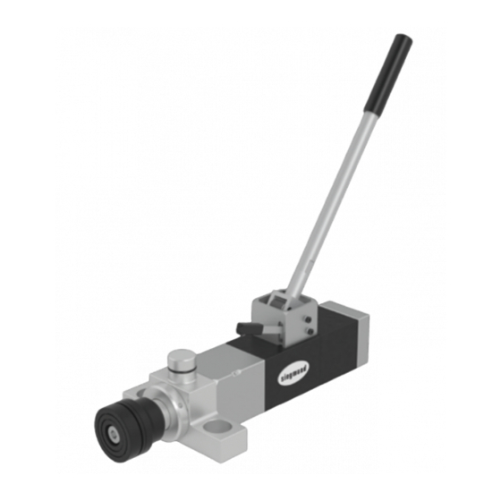
Lever Clamping Spot Clamping Lever Absorption Pic. 1: Instructions (Pic. Shows Version 28) SAFETY INSTRUCTIONS Pay attention to the following instructions to avoid malfunction material damages and physical damages 2.1. INTENDED USE The intended use of the unit is the clamping of work pieces with a clamping force of max 25.000 N inside an external absorption. -
Page 7: Secure Handling
→ Correct handling and paying attention to the assembly and operating instructions are essential for the productivity reliability and work security. → If the unit shows damages or leakings, it shoud be shut down immediately. → The maximum intendet clamping force is 25 KN, it must not be exceed. Exceedings can leed to serious damage on the unit and physical damages. -
Page 8: Scope Of Delivery
CAUTION Slight risk of injury • During transportation, don’t carry the unit on the rubber grommt of the lever. It could loosen and the unit may fall down. • Wear safety clothes and safety equipment while operating hydraulic units. • Wear protective gloves and safety shoes while working with the unit. •... -
Page 9: Assemby
NOTICE Mounting absorptions are not included in the scope of delivery and should be coordinated individually with the manufacturer. INSTALLATION The lever is split in two parts for smoother handling (Pic. 3). Please use the machined area of coverage on the lever to firmly screw it on to the absorption. M10 standard thread Spanner flat 13 mm Spanner flat lever... - Page 10 CAUTION Danger of physical damage, caused by oil spillage Danger of physical damage, caused by loosened lever • Don’t drill additional holes in to the unit to install additional absorptions! • Wear safety glasses to avoid eye injuries! • The hand lever is moving. Pay attention when mounting the unit to avoid squeezing of skin parts.
-
Page 11: Structural Requirements
The front absorption on Version 16 and Version 28 is designed rotatable. By turning in any direction, one can switch between two different alignment positions. The alignment is locking 90° shifted. Pic. 5: Illustration 4.1. STRUCTURAL REQUIREMENTS • Prior to installation, make sure that the installation measurements and installation conditions are matching the components of the unit. -
Page 12: Operating
Version 16 Version 28 ca. 20° lower senken approx. 20° ø32 Pic. 6: Construction Dimensions 4.2. OPERATING Operate the unit with the hand grip of the pump lever and with the down lever. → While operating the unit, wear safety gloves. →... - Page 13 CAUTION Obstructions during extending and lowering can lead to squeezing! → Prior to operating the operating lever, make sure no obstructions are blocking the travelling distance. NOTICE Pay attention to clean and dry operating elements while operating the unit. Support area Pump lever Lower lever Pic.
-
Page 14: Clamping Hydraulic, Extending And Retracting
4.3. CLAMPING HYDRAULIC, EXTENDING AND RETRACTING pump ca. 75° pumpen about 75° lower ca. 20° senken approx. 20° Pic. 8: Functional area of the pump lever and lowering lever 4.3.1. EXTENDING Push the pump lever in regular working speed up to the stopper in pumping direction. Max. -
Page 15: Retracting
With reaching the upper stop position, no additional pressure will build up. The force on the pump lever stays unchanged. The piston rod may move a little over the end position and will then lower just about 2 mm. This is a normal operating condition. NOTICE Depending on pressure and stroke, the actuating force during pumping will change. -
Page 16: Troubleshooting
CAUTION Obstructions during extending and lowering can lead to squeezing! Squeezing danger: During lowering the piston rod will accelerate by applied forces. High force and high speed can develop. TROUBLESHOOTING DISTURBANCE CAUSE SOLUTION Short-term pressure build Over travel of the overflow Operator tries to create tension with far up only extended piston rod. -
Page 17: Overload Safetys
FEHLER URSACHE LÖSUNG Unit does not keep Pressure Hydraulic system may Pumping jerkily with open and closed be polluted lowering valve. Produce strong internal oil flow to flush pollutants of the valve seating. Repeat this procedure several times. Temperature fluctuations The unit is a closed system which is acting to temperature fluctuations because of its tightness. -
Page 18: Maintenance And Inspection
SYSTEM 2 Pressure safety with bursting element Bursting elements are pressure protections which secure pressure leading systems against dangerous excess pressure. It occurs in bursting of a bursting disc, which is consisting of metal foil. In case of the acting of an external force to the piston rod, by example an additional hydraulic, an excessive distortion of the work piece, the pressure safety will be destroyed. -
Page 19: Inspections
NOTICE Damage of the unit trough self-repair! → Contact your distributor in case of repair. → Order spare parts through you distributor only. → Retain a specialist, trained on this unit. DANGER Pre stressed spring! Injuries caused by the pre stressed spring unit. →... -
Page 20: Disposal
DISPOSAL Disposal of the hydraulic and oil Packaging material should be conveyed to an environment friendly recycling. DANGER Pre stressed spring! Injuries caused by the pre stressed spring unit. → Open the unit only if appropriate safety measures are applied to the construction elements. -
Page 21: Technical Data
TECHNICAL DATA CLAMPING HYDRAULIC VALUE Maximum stroke 60 mm Weight of the unit 5,78 kg Maximum clamping force 25 kN Holding time (clamping force) Min. 30 Min under constant temperature Max. allowed operating pressure 315 bar Quantity pump strokes to reach stroke 60 mm ~ 14 Hub per pump stroke ~ 4,6 mm... -
Page 22: Hydraulic Diagram
8.1. HYDRAULIC CIRCUIT PLAN Cylinder Bursting disc RSV 2 Lowering valve Hand pump RSV 1 Pic. 10: Hydraulic circuit plan... -
Page 23: Type Plate
8.2. TYPE PLATE Position of the type plate Identification and serial number Pic. 11: Position of the type plate The type plate is mounted to the basic body or directly inscribed respectively. The serial number and the product identification is located on the type plate. NOTICE →... - Page 26 Our General Business Terms apply. Subject to price changes and printing errors. All texts, pictures and design elements are copyrighted by the Bernd Siegmund GmbH. No part of this flyer may be edited analogously or digital or in another mode,...
Need help?
Do you have a question about the System 16 and is the answer not in the manual?
Questions and answers