
Summary of Contents for Meler Macro Series
- Page 1 GLUING SOLUTIONS ADHESIVE INSTRUCTIONS MANUAL MELTER MACRO SERIES MA-5052-ENG 221220...
- Page 2 Published by: Focke Meler Gluing Solutions, S.A. Pol. Arazuri-Orkoien, c/B, nº3 A E-31170 Arazuri - Navarra - Spain Phone: +34 948 351 110 info@meler.eu - www.meler.eu Focke Group Edition December 2020 © Copyright by Focke Meler All rights reserved. Its reproduction, diffusion or use by electronic or other means of all or any part of this document without the express authorization of its owner is strictly prohibited.
-
Page 3: Table Of Contents
TABLE OF CONTENTS MA-5052-ENG MACRO SERIES MELTER MANUAL TABLE OF CONTENTS 1. SAFETY GUIDELINES General Symbols Mechanical components Electrical components Hydraulic components Pneumatic components Thermal components Materials Noise emission declaration Intended use Limited use 2. INTRODUCTION Description Intended use Limited use... - Page 4 FOCKE MELER GLUING SOLUTIONS TABLE OF CONTENTS Installation requirements Free space Electrical Consumption Compressed air Other factors Unpacking Contents Mounting the equipment Electrical power connection Pneumatic connection Hose and applicator connection Parameter Programming Programming working temperatures Selecting the overheating value...
- Page 5 TABLE OF CONTENTS MA-5052-ENG MACRO SERIES MELTER MANUAL Melter equipment displays Displaying the temperature for each component Alarm displays Hot-melt display level (optional) Display and adjustment of the working speed Temperature adjustment Programming the applicator parameters Setting the clock Programming the current day and hour...
- Page 6 FOCKE MELER GLUING SOLUTIONS TABLE OF CONTENTS Configuring speed ramp 4-22 Programming speed ramp 4-23 Current Vin voltage display 4-24 By-pass valve regulation 4-24 Manual valve control 4-25 Pneumatic valve control 4-25 Turning off the melter equipment 4-25 5. MAINTENANCE...
- Page 7 TABLE OF CONTENTS MA-5052-ENG MACRO SERIES MELTER MANUAL 6. TECHNICAL CHARACTERISTICS General Dimensions Accessories Pneumatic by-pass valve pressure control system Light tower system Level control system Automatic tank filling system 7. ELECTRICAL DRAWINGS 8. PNEUMATIC DIAGRAMS Components list Pneumatic by-pass valve control system (optional) 9.
- Page 8 FOCKE MELER GLUING SOLUTIONS TABLE OF CONTENTS This page is intentionally left blank.
-
Page 9: Safety Guidelines
SAFETY GUIDELINES MA-5052-ENG MACRO SERIES MELTER MANUAL 1. SAFETY GUIDELINES General The information contained in this section applies not only to everyday equipment operation, but also to any procedure carried out on it, whether for preventive maintenance or in the case of repairs and the replacement of worn out parts. -
Page 10: Mechanical Components
FOCKE MELER GLUING SOLUTIONS SAFETY GUIDELINES Mechanical components The hot-melt installation, which is installed to this device, requires moving parts that can cause damage. Use the equipment correctly, and do not remove the safety guards while the equipment is in operation; prevent the risk of possible entrapment due to moving mechanical parts. -
Page 11: Thermal Components
Safety Information Sheet of the adhesive. Materials Meler systems are designed for use with hot-melt adhesives. They should not be used with any other type of material, and especially not with solvents, which may cause personal injury or damage to internal system components. -
Page 12: Intended Use
Note: Do not modify the equipment or use components that were not supplied by Meler. For any modification of a component of the equipment or part of the installation, you must firstly consult the After-Sales Service... -
Page 13: Introduction
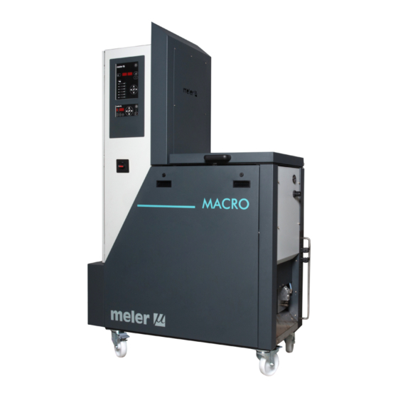
In this manual you will find information about the installation, use and maintenance of the hot-melt adhesive melter in meler’s Macro series. The Macro series includes the 50 and 120 liter range of hot-melt adhesive melters. Most of the photographs and illustrations that appear in this manual refer to the 50-liter Macro melter. -
Page 14: Description
– cover a wide range of applications, being very versatile in all markets where they are used. Intended use The hot-melt melters in the Macro series are designed to be used in the following conditions: • Hot-melt adhesive fusion and pumping at temperatures up to 200°C. -
Page 15: Hot-Melt Melter Identification
INTRODUCTION MA-5052-ENG MACRO SERIES MELTER MANUAL Control of internal pumping and external speed_Switches in the position ok ‘int’ and ref ’ext’. This mode of operation is performed through internal pumping control and speed control by means of an external 0-10 V signal sent from the main machine. -
Page 16: Main Components
FOCKE MELER GLUING SOLUTIONS INTRODUCTION Main components... - Page 17 INTRODUCTION MA-5052-ENG MACRO SERIES MELTER MANUAL 1. Front control card. 2. Access door to the electronic section and connections. 3. Pumping control card. 4. Main power switch. 5. Electrical main supply input. 6. Unit transport wheels. 7. Tank access cover.
-
Page 18: Control Card Components
FOCKE MELER GLUING SOLUTIONS INTRODUCTION Control card components 1. Tank indicator LED. 2. Applicator indicator LED. 3. Temperature set point. 4. Real temperature. 5. ON/OFF switch. 6. Standby function. 7. Temperature OK LED. 8. Time scheduling. 9. Left/right button - channel selection. -
Page 19: Pumping Control Card Components
INTRODUCTION MA-5052-ENG MACRO SERIES MELTER MANUAL Pumping control card components 1. Main switch ON/OFF. 2. External start-stop LED. 3. External speed control LED. 4. Pumping permission LED. 5. Up/down arrow keys for selecting values. 6. Left/right arrow keys for selecting options. -
Page 20: Optional Equipment
FOCKE MELER GLUING SOLUTIONS INTRODUCTION Optional Equipment In order to provide the melting equipment with more functions, the following optional elements may be added: • Pneumatic by-pass valve pressure control system. • Light tower system. • Low melted adhesive level detection system. -
Page 21: Installation
Introduction The Macro series melters are delivered with all the materials necessary for their installation. However, some components must be provided by the user himself, according to the location and connections in each particular installation: •... -
Page 22: Electrical Consumption
350 kg 535 kg Electrical Consumption In order to install a Macro series melter, we should take into consideration the total consumption of the installation, including the consumption of the installed hoses and applicators. Before connecting, make sure that the voltage that is being connected to the melter is the correct one appearing on the equipment’s characteristics plate. -
Page 23: Other Factors
• Connector for external I/O (included on the power card). Mounting the equipment The Macro series melting equipment are equipped with wheels for their easy transport and positioning near the main machine. The four wheels turn 360°, and two are equipped with brakes. To move the unit, unlock the two wheels by lifting the lever. -
Page 24: Electrical Power Connection
FOCKE MELER GLUING SOLUTIONS INSTALLATION Electrical power connection Macro series melters are designed to be connected to the electrical power supply in 3-phase 400 VAC with neutral. A good ground connection is required in any case. Consumption figures, according to melter and output configuration, are included in the table. -
Page 25: Hose And Applicator Connection
Once the melter and its components are installed, you will need to program the operational parameters appropriate for the specific application that will be performed. Macro series melters simplify this task as much as possible, allowing the operator to modify only those parameters that are necessarily variable for each application. -
Page 26: Programming Working Temperatures
FOCKE MELER GLUING SOLUTIONS INSTALLATION Among the various parameters, it is necessary to program the set point temperature values for each component connected and the value for overheating warnings. There are two other parameters (weekly start-up and shut-down programming and the standby temperature value) left to program in advanced systems, although the factory default values are perfectly valid for operational purposes. -
Page 27: Keeping A Component On Display
INSTALLATION MA-5052-ENG MACRO SERIES MELTER MANUAL The value displayed corresponds to the increase in real temperature over the set point temperature permitted without activating the alarm message. 4. Use the right arrow to advance to the next screen. 5. Exit the special menu using the left arrow and the tank temperatures will once again be displayed. -
Page 28: Temperature Ok
FOCKE MELER GLUING SOLUTIONS INSTALLATION • Output disabled_disabled input signal for each hose-applicator output via a non-voltage contact. With a closed contact, the output remains activated (output on); with an open contact, it is deactivated (output off). • Motor start up_for each pump installed, the motor start up may be controlled by closing an external non-voltage contact. -
Page 29: Low Level (Optional)
INSTALLATION MA-5052-ENG MACRO SERIES MELTER MANUAL contact NO contact NO 4. Reconnect the card connector. 5. Make sure that the cable is well connected and that its path through the electrical cabinet presents no risks of snagging, being cut or any other accidental deterioration. -
Page 30: Starting Up The Motor (Ok Ext)
FOCKE MELER GLUING SOLUTIONS INSTALLATION 3. Remove the connector from the card and connect the two cable wires to their corresponding connector terminals: 1 common + voltage output 2 input for inhibitor output 1 3 input for inhibitor output 2... -
Page 31: Motor Speed Set Point Reference (Ref Ext)
INSTALLATION MA-5052-ENG MACRO SERIES MELTER MANUAL Motor speed set point reference (ref ext) 1. If this is the only signal being connected, use 0.5 mm two-wire cable. 2. Thread the power cord (max. Ø12.5 mm) through the electrical wall bushing Pg13 and fasten it to the inside anchor, making sure that the cord reaches the power card connector. - Page 32 FOCKE MELER GLUING SOLUTIONS INSTALLATION This page is intentionally left blank. 3-12...
-
Page 33: Melter Operation
MELTER OPERATION MA-5052-ENG MACRO SERIES MELTER MANUAL 4. MELTER OPERATION In this section we will introduce the method for using the melter. Although its operation is very simple, it should not be used by untrained personnel. Warning: Improper use may cause damage to the machine or injury and even death to the person using it. -
Page 34: Starting Up The Melter Equipment
FOCKE MELER GLUING SOLUTIONS MELTER OPERATION To fill the tank: 1. Open the tank lid. 2. Use a shovel or a ladle to fill the tank with adhesive. Do not fill the tank above the loading opening level. The lid must be able to close normally. -
Page 35: Melter Equipment Displays
MELTER OPERATION MA-5052-ENG MACRO SERIES MELTER MANUAL not reached 3° below its temperature setting point, the LEDs turn off. If the system is shut down, for any possible mode, when it is turning on the delay timer only starts again if the tank temperature is 20° below setting point. -
Page 36: Displaying The Temperature For Each Component
FOCKE MELER GLUING SOLUTIONS MELTER OPERATION Displaying the temperature for each component The temperature may be displayed for each component (premelter, tank, distributor and each hose and applicator) by selecting the component with the cursor. Press the left-right arrow until the desired component is displayed. -
Page 37: Alarm Displays
MA-5052-ENG MACRO SERIES MELTER MANUAL Alarm displays Macro series melter equipment tell the user when a malfunction has occurred in the unit, sending warning messages that may be seen on the control panel display. When an alarm appears, the control unit takes a series of steps to protect the unit. -
Page 38: Hot-Melt Display Level (Optional)
FOCKE MELER GLUING SOLUTIONS MELTER OPERATION Hot-melt display level (optional) If the equipment is fitted with a level detector, and the hot-melt level drops below the programmed level (capacitive detector), a signal is sent to the melter control which launches the following actions: 1. -
Page 39: Programming The Applicator Parameters
MELTER OPERATION MA-5052-ENG MACRO SERIES MELTER MANUAL The general process for adjusting the temperatures of each components is described below. 1. Select the component whose value you wish to modify using the left- right arrow. The tank and the distributor have the same set point value. -
Page 40: Setting The Clock
FOCKE MELER GLUING SOLUTIONS MELTER OPERATION The value shown corresponds to the percent decrease in the real temperature compared to the set point temperature that will occur when this function is activated. 7. Use the right arrow to go to the next display where delay time value ƒ... -
Page 41: Programming Equipment Activation/Deactivation
MELTER OPERATION MA-5052-ENG MACRO SERIES MELTER MANUAL . 0 8 . 0 8 On the left display, you will see the time with a dot, indicating that this is the value that may be modified, while the minutes appear on the second display. -
Page 42: Disabling The Equipment Activation/Deactivation Program
FOCKE MELER GLUING SOLUTIONS MELTER OPERATION 0 7 . 2 0 7 . 2 1 9 . 3 1 9 . 3 4. The blinking dot next to the start time indicates that this is the value that may be modified. Use the up-down arrow to select the desired value. -
Page 43: Programming The Equipment's Standby Function Activation/Deactivation
MELTER OPERATION MA-5052-ENG MACRO SERIES MELTER MANUAL Programming the equipment’s standby function activation/deactivation You may program an activation and a deactivation time for every day of the week, from Monday (1) to Sunday (7). Time is expressed in 15 minute increments, so we cycle from 10.0 (10 hours and 0 minutes) to 10.1 (10 hours... -
Page 44: Disabling The Equipment Standby Function Programming
FOCKE MELER GLUING SOLUTIONS MELTER OPERATION 8. Press the button with the clock symbol once again. The selected program appears once again. You may use the up-down arrow to select other programs. 9. Pressing either the left or the right arrow button will exit this program and return to the tank temperature display. -
Page 45: Pumping Control
MELTER OPERATION MA-5052-ENG MACRO SERIES MELTER MANUAL and the standby mode. Using the standby function during periods of melter inactivity helps save energy and allows the heated elements to return quickly to their set point temperatures once you return to the operational mode. -
Page 46: Pumping Safety Measures
FOCKE MELER GLUING SOLUTIONS MELTER OPERATION • Should the 24 Vdc power supply to the control card be lost, on recovering the power supply the control card will remain turned off until pumping permission input is activated. If on recovering the power supply the pumping permission input is activated, it will turn on directly. -
Page 47: Password Security
MELTER OPERATION MA-5052-ENG MACRO SERIES MELTER MANUAL To deactivate pump safety see the section ‘User configuration menu’, paragraph 5. Password security If the option selected in the password security configuration is ‘1’, security enabled, only the control card ON/OFF and pumping ON/OFF buttons will be operational. -
Page 48: Modes Of Operation
FOCKE MELER GLUING SOLUTIONS MELTER OPERATION 6. Ext ref LED: when operating in external reference mode and the external reference voltage is other than zero, this LED will be illuminated. When the external reference voltage is zero, this LED will be turned off. This LED is green in colour. -
Page 49: Mode Of Operation With Internal Pumping Control And External Speed Control
MELTER OPERATION MA-5052-ENG MACRO SERIES MELTER MANUAL 3. Using the up/down arrows, select the rotation speed and/or wait for pumping permission to be enabled (red LED is turned off). At this moment, the pump will start to rotate at the speed indicated on the display. -
Page 50: Mode Of Operation With External Pumping Control And Internal Speed Control
FOCKE MELER GLUING SOLUTIONS MELTER OPERATION The system will wait for the speed signal from the main machine. When the signal has been received, if a speed has been previously set it will appear on the display and the pump will begin to rotate at the indicated speed. -
Page 51: Mode Of Operation With External Pumping Control And External Speed Control
MELTER OPERATION MA-5052-ENG MACRO SERIES MELTER MANUAL • That the failure input is not activated (E5), in which case starting the pump would be impossible. In case of the pump be operating and this input is activated, pumping will cease immediately. - Page 52 ‘User configuration menu’, ‘1. MAXIMUM RPM’. The pump control card is designed with certain parameters programmed at Meler that can be modified if necessary to meet your requirements. Modifications may be made through the ‘User configuration menu’ and programming speed ramp menus.
-
Page 53: User Configuration Menu
MELTER OPERATION MA-5052-ENG MACRO SERIES MELTER MANUAL User configuration menu To open this menu, press simultaneously the left arrow key, the right arrow key, and ON/OFF button of the pump control card. If the security password is enabled, the security password must be entered to access this menu. -
Page 54: Minimum Rpm Alarm
FOCKE MELER GLUING SOLUTIONS MELTER OPERATION Minimum rpm alarm This alarm will be triggered when the motor rotates at a speed that is below the MINIMUM RPM ALARM for the period established in the MINIMUM RPM ALARM TIME field. • When this alarm is triggered, an ‘E.L.’ error is shown on the control card. -
Page 55: Programming Speed Ramp
MELTER OPERATION MA-5052-ENG MACRO SERIES MELTER MANUAL Notes on the editable values in the conversion table: • The value for voltage must always be shown to one decimal place. • Point 1 is the starting point for the speed ramp, and therefore the voltage will always be 0, while the value for output RPM is editable. -
Page 56: Current Vin Voltage Display
FOCKE MELER GLUING SOLUTIONS MELTER OPERATION 000 to MAXIMUM RPM; press the right arrow key to go to the next point: The IN LED to the position ON and the OUT LED to the position OFF, 3 XXX, which means that the input voltage value is being programmed for point 3;... -
Page 57: Manual Valve Control
MELTER OPERATION MA-5052-ENG MACRO SERIES MELTER MANUAL in the connectors, the diameters of the nozzle outputs, etc.) and the adhesive itself (its viscosity). For safety reasons, this pressure must be discharged when the circuit exceeds the operating value (normally with a closed circuit and the pump activated), which makes the use of a discharge valve or a by-pass valve necessary. - Page 58 FOCKE MELER GLUING SOLUTIONS MELTER OPERATION This page is intentionally left blank. 4-26...
-
Page 59: Maintenance
Check thermostats operating - Checking while working Thermostats maintenance If the equipment does not work or works incorrectly, called to your Meler Representative or to the Main Office. Equipment cleaning To continue to take advantage of the melter’s benefits and to ensure the perfect mobility of its components, it is necessary to keep all its parts clean, especially the ventilation grate on the upper part of the machine. -
Page 60: Depressurizing The System
FOCKE MELER GLUING SOLUTIONS MAINTENANCE Removing and changing exterior panels: 1. Disconnect the melter equipment. 2. Disconnect the compressed air from the equipment intake. 3. Turn counterclockwise 1/4 turn the two screws holding the panel. 4. Tilt the panel and pull it up by means of two handles placed below fixing screws. -
Page 61: Tank Filter
MAINTENANCE MA-5052-ENG MACRO SERIES MELTER MANUAL No rule exists for determining when to change the filter. Several factors influence this decision: • The type and purity of the adhesives used. • The adhesive work temperatures. • Adhesive consumption in relation to the time it spends in the tank. -
Page 62: Cleaning The Tank
FOCKE MELER GLUING SOLUTIONS MAINTENANCE 1. Remove four screws that fix the assembly. 2. Take out the filter using the holding ring at the end of the filter. 3. Clean the grid of dirty and burnt adhesive. 4. Replace the o-ring if it is damaged. -
Page 63: Emptying The Tank
MAINTENANCE MA-5052-ENG MACRO SERIES MELTER MANUAL Warning: Use appropriate protective equipment for high temperatures. 3. Add the appropriate type and quantity of adhesive and wait for it to melt. 4. Remove the filter cartridge and clean it, if necessary (see the section ‘Filter maintenance’). -
Page 64: Pump Maintenance
FOCKE MELER GLUING SOLUTIONS MAINTENANCE Warning: Use appropriate protective equipment for high temperatures. Pump maintenance Inspecting for leaks The pump is equipped with a gasket system on the shaft to prevent adhesive from leaking through it. On occasion, some adhesive may leak out, which makes it necessary to retighten the screws or change the gasket. -
Page 65: Recommended Lubricants
MAINTENANCE MA-5052-ENG MACRO SERIES MELTER MANUAL Recommended lubricants Brand Type of grease Telesia Compound A SHELL Tivela Compound A MOBIL Glygoyle Grease 00 Brand Type of oil KLÜBER Klübersynth GH 6-220 SHELL Tivela Oil S 220 MOBIL Glygoyle 30 Thermostats maintenance... - Page 66 FOCKE MELER GLUING SOLUTIONS MAINTENANCE This page is intentionally left blank.
-
Page 67: Technical Characteristics
TECHNICAL CHARACTERISTICS MA-5052-ENG MACRO SERIES MELTER MANUAL 6. TECHNICAL CHARACTERISTICS General Tank capacity 50 liters 120 liters Pumping rate (*) single pump 1, 2.5, 4, 8, 15, 20 y 30 cc/rev 1, 2.5, 4, 8, 15, 20 y 30 cc/rev double pump (per output) 2x0.93, 2x1.86, 2x3.71 y 2x4.8 cc/rev... -
Page 68: Dimensions
FOCKE MELER GLUING SOLUTIONS TECHNICAL CHARACTERISTICS Dimensions Macro 50 1150 Macro 120 1150... -
Page 69: Accessories
NO (normally open) contact, with no voltage. Automatic tank filling system Meler pellet loaders ensure a continuous level of adhesive inside the tanks of the melting units, eliminating the need for manual loading by the user. - Page 70 FOCKE MELER GLUING SOLUTIONS TECHNICAL CHARACTERISTICS This page is intentionally left blank.
-
Page 71: Electrical Drawings
ELECTRICAL DRAWINGS MA-5052-ENG MACRO SERIES MELTER MANUAL 7. ELECTRICAL DRAWINGS... - Page 72 FOCKE MELER GLUING SOLUTIONS ELECTRICAL DRAWINGS This page is intentionally left blank.
-
Page 73: Pneumatic Diagrams
PNEUMATIC DIAGRAMS MA-5052-ENG MACRO SERIES MELTER MANUAL 8. PNEUMATIC DIAGRAMS Components list Pneumatic by-pass valve control system (optional) Pressure regulator 1-10 bar. Pressure gauge 0-10 bar. Pneumatic limit control valve. REGULADOR DE PRESIÓN MANÓMETRO PRESSURE REGULATOR MANOMETER P: 0-10 bar P: 0-10 bar VÁLVULA LIMITADORA / PRESSURE LIMIT VALVE... - Page 74 FOCKE MELER GLUING SOLUTIONS PNEUMATIC DIAGRAMS This page is intentionally left blank.
-
Page 75: Spare Parts List
MACRO SERIES MELTER MANUAL 9. SPARE PARTS LIST The most common spare parts list of the Macro series adhesive melters is shown in this chapter to give you a quick and sure guideline to choose them. The spare parts are listed by groups in a natural order as they are located on the units. -
Page 76: Cover- Tank Assembly
HOJA Nº/ MACRO 50 SHEET NUMBER 1 de 1 Este plano es propiedad exclusiva de MELER APLICADORES DE HOT - MELT S.A. Todos los derechos rese This drawing is owned sole of MELER APLICADORES DE HOT- MELT S.A. All rights reserved. -
Page 77: Simple/ Double Distributor Assembly
SPARE PARTS LIST MA-5052-ENG MACRO SERIES MELTER MANUAL B. SIMPLE/ DOUBLE DISTRIBUTOR ASSEMBLY Nº Ref. Description 150027950 Complete two 3/4” hydraulic outputs block 150023950 O-ring Ø24x2 10100082 Pump plug with o-ring 10100083 Pump plug o-ring 150027960 Pump 3/4” plug with o-ring 150041920 Pump 3/4”... -
Page 78: Filter And Pressure Valve Assembly
FOCKE MELER GLUING SOLUTIONS SPARE PARTS LIST C. FILTER AND PRESSURE VALVE ASSEMBLY Nº Ref. Description 150026260 Mechanical pressure valve assembly 150026270 Pneumatic pressure valve assembly (*) 150026280 Mechanical pressure valve o-rings 150026290 Mechanical pressure valve spring 150026060 Pressure valve closure needle... -
Page 79: Geared Motor-Pump Assembly
SPARE PARTS LIST MA-5052-ENG MACRO SERIES MELTER MANUAL D. GEARED MOTOR-PUMP ASSEMBLY Nº Ref. Description 150025960 Single gear pump 1cc/rev seat Ø79 150114020 Single gear pump 2.5cc/rev seat Ø79 150025930 Single gear pump 4cc/rev seat Ø79 150025970 Single gear pump 8cc/rev (Plate seat Ø79) -
Page 80: Electrical Cabinet
FOCKE MELER GLUING SOLUTIONS SPARE PARTS LIST E. ELECTRICAL CABINET Nº Ref. Description 150028140 PG 21 cable gland 10140040 PG 13.5 cable gland 150113660 Control board 150117100 Pumping control card 150113680 Power control board 6 outputs 150113670 Power control board 2 outputs... - Page 81 SPARE PARTS LIST MA-5052-ENG MACRO SERIES MELTER MANUAL 18.1 23 24...
- Page 82 FOCKE MELER GLUING SOLUTIONS SPARE PARTS LIST This page is intentionally left blank.
-
Page 83: Ec Declaration Of Conformity
EC DECLARATION OF CONFORMITY Original Declaration The manufacturer, Focke Meler Gluing Solutions, S.A. Pol. Los Agustinos, c/G, nave D-43 E-31160 Orkoien, Navarra - Spain — Focke Group — declaring that the machinery, Type: Model: Serial Number: fulfils all the relevant provisions of the Directive 2006/42/EC on machinery,... - Page 84 For more information speak with your Focke Meler representative: Focke Meler Gluing Solutions, S.A. Pol. Arazuri-Orkoien, c/B, nº3 A E-31170 Arazuri - Navarra - Spain Phone: +34 948 351 110 info@meler.eu - www.meler.eu Focke Group...
Need help?
Do you have a question about the Macro Series and is the answer not in the manual?
Questions and answers