
Summary of Contents for AVANT A37190
- Page 1 English Multi function drive unit 2021 1 Operator's Manual for Attachment Multi function drive unit Product number A37190 www.avanttecno.com A438836 2021 1 EN 2018-...
- Page 2 Multi function drive unit 2021 1...
-
Page 3: Table Of Contents
Multi function drive unit 2021 1 CONTENTS 1. FOREWORD ............................5 Warning symbols used in this manual ........................... 6 2. DESIGNED PURPOSE OF USE......................7 3. SAFETY INSTRUCTIONS FOR USING THE MULTI FUNCTION DRIVE UNIT ......8 4. TECHNICAL SPECIFICATIONS ....................... 12 Rotating speed ................................ - Page 4 7.10 XL weed brush ................................53 7.10.1 Using the XL weed brush ..........................54 7.10.2 Storage of the weed brush ..........................54 7.11 Wire rope brush ................................ 55 7.11.1 Using the wire rope brush ..........................56 8. MAINTENANCE AND SERVICE ....................... 57 Inspection of hydraulic components ........................
-
Page 5: Foreword
If you sell or transfer the equipment, be sure to hand over this manual to the new owner. If the manual is lost or damaged, you can request a new one from your Avant dealer or from the manufacturer. -
Page 6: Warning Symbols Used In This Manual
6 (66) Warning symbols used in this manual The following warning symbols are used throughout this manual. They indicate factors that must be taken into account to reduce the risk of personal injury or damage to property: WARNING SAFETY ALERT SYMBOL This symbol means: “Warning, be alert! Your safety is involved!”... -
Page 7: Designed Purpose Of Use
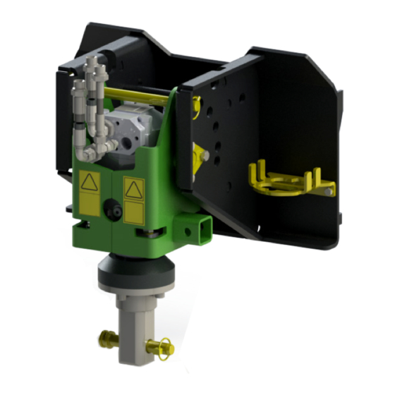
2. Designed purpose of use The AVANT Multi function drive unit is an attachment that is suitable for use with AVANT compact loaders that are shown in Table 1. The strong and robust hydraulically rotated multi purpose drive unit is equipped with square shaft and pin locking system, which enables to use different work tools. -
Page 8: Safety Instructions For Using The Multi Function Drive Unit
8 (66) 3. Safety instructions for using the multi function drive unit Please bear in mind that safety is the result of several factors. The loader-attachment combination is highly powerful and improper or careless use or maintenance may cause serious personal injury or property damage. - Page 9 9 (66) Risk of tipping over - Always transport the attachment as low and close to the machine as possible to keep the centre of gravity low. On slippery surfaces drive slowly and deliberately. Operate the controls of the loader slowly and calmly especially on inclined terrain.
- Page 10 10 (66) Risk of entanglement and crushing - Stop the attachment before cleaning or removing blockages. The attachment can start to rotate immediately after a blockage is removed. Always follow the safe stopping procedure to prevent all rotating parts from DANGER moving when clearing a blockage.
- Page 11 11 (66) Safe stopping of the attachment, before going near the attachment: Always stop the attachment following safe stopping procedure before leaving the driver's seat. Safe stopping procedure prevents all unintentional movements of the attachment. Note that the loader boom can move down even if the engine of the loader is turned off.
-
Page 12: Technical Specifications
1355 Nm Weight: 80 kg Tool fixing: 57 mm, square 30-60 l/min Hydraulic energy input: 20 MPa (200 bar) Suitable AVANT loaders: See table 1 A37323 Angle adapter, 90°: See page 21 Available drive tools: See table 3 4.1 Rotating speed Different work tools are operated at different speeds. -
Page 13: Work Tools For The Drive Unit
Shown below in Table 3 are the work tools for the Multi function drive unit. Changes to availability are possible, ask your Avant dealer for latest information or see Avant website. For detailed information about each tool, see the related page in this manual. -
Page 14: Safety Labels And Main Components Of The Attachment
14 (66) 4.3 Safety labels and main components of the attachment Listed below are the labels and markings on the attachment. They must be visible and readable on the equipment. Replace any unclear or missing label. New labels are available via your retailer or contact information provided on the cover. - Page 15 Keep a safe distance and follow safe stopping procedure. 5 A420014 Attachment identification plate Table 5 - Multi function drive unit - Main components Frame with Avant quick coupling brackets Tool shaft, square Tool locking pin Locking pin Drive motor cover...
-
Page 16: Assembling The Attachment
Do not stay in the area between the attachment and the loader. Mount the attachment only on level surface. WARNING Never move or lift an attachment that has not been locked. Avant quick coupling system: Step 1: Lift the quick attach plate locking pins up and turn them backwards into the slot so that they are locked in the upper position. -
Page 17: Connecting And Disconnecting Hydraulic Hoses
5.1 Connecting and disconnecting hydraulic hoses On Avant loaders the hydraulic hoses are connected using the multi connector system. If you have an Avant 300-700 series loader with the conventional quick couplers and wish to change to the multi connector system, contact your Avant dealer or service point for instructions or installation services. - Page 18 18 (66) The lever should move easily all the way to its locking position. If the lever does not slide smoothly, check the alignment and position of the connector and clean the connectors. Also shut down the loader and release the residual hydraulic pressure.
-
Page 19: Operating The Attachment
19 (66) 6. Operating the attachment Check the attachment and the operating environment once more before starting to work, and that all obstacles have been removed from the operating area. Quick inspection of the equipment and the operating area before use are parts of ensuring safety and the best performance of the equipment. -
Page 20: Checks Before Use
20 (66) Risk of crushing - Going under the loader boom or an attachment can cause serious injury or death. Never go under the loader boom and prevent others from getting near DANGER lifted boom or attachment. Going under a raised attachment or loader boom is dangerous, as the boom may lower due to loss of stability, mechanical fault or when other person operates the controls of the loader. -
Page 21: Adjustments
21 (66) Regularly clean the loader oil cooler core; refer to the operator's manual of the loader for more instructions. Overheating oil decreases the power and affects the service life of the hydraulic components of both the attachment and the loader. 6.2 Adjustments Because the multi function drive unit can be adjusted in different angles, it can be fitted with various work tools. -
Page 22: Side Shift - Angle Adapter 90
22 (66) 6.2.2 Side shift - Angle adapter 90° The angle adapter A37323 makes it possible to mount the Multi function drive unit so that it is turned 90 degrees to the left. With the angle adapter the carousel broom sweeps on the left side of the loader, for instance, and the cable/hose reel is crosswise to the loader and winds the cable longitudinally (in parallel to the loader). -
Page 23: Working On Uneven Ground
23 (66) 6.2.3 Working on uneven ground Extra caution is needed when using the equipment on inclined terrains and slopes. Drive slowly especially on inclined, uneven, or slippery surfaces, and avoid sudden changes in speed or direction. Operate the controls of the loader with careful and smooth movements. -
Page 24: Storage
24 (66) 6.4 Storage See storage instructions of each work tool shown separately in this manual. Usually the work tools should be removed from the Drive unit and stored separately. To store the Drive unit without any work tool fitted: Place the locking pin to lock the drive unit to a forward pointing position for the best stability during storage. -
Page 25: Using The Work Tools
Risk of wrong use - Always read the instructions related to each tool. Each work tool is used in a different way and may introduce risks that you need to take into account when using the Multi function drive unit with a work tool. Use only Avant work tools. WARNING 7.1 Changing of work tools... -
Page 26: Auger Tools
100 mm to 300 mm range depending on the type of soil. The larger augers work best when operated on area where there are no larger stones. For more demanding conditions or larger auger sizes, consider using the Avant HD Auger drive units that are equipped with a planetary gearbox, which can provide more torque. -
Page 27: Using The Auger
27 (66) 7.2.1 Using the auger Before starting to use the auger: Plan the drilling operation in advance. Make sure that it is safe to dig at the area. Explore the operating area and find out about the possibility of having any electric cables, water mains, gas pipes, communications cable or similar buried in the ground before starting to drill. - Page 28 28 (66) 7.2.1.1 Transportation of the auger unit Make sure the locking pin of the angle adjustment of the Drive unit is in place to prevent swinging of the drive unit during transport. If the drive unit is left to swing freely, the auger can hit the ground or swing up. If the auger hits the ground, the blade bits may crack or other damage may result.
- Page 29 29 (66) 7.2.1.2 Fitting an auger tool and using extension shafts The auger tools can be fitted when the drive unit is locked to the loader so that the position of the auger can be controlled with the loader. The auger tools should be fitted after arriving at the operating area, to decrease the possibility of uncontrolled swinging of the drive unit while driving.
- Page 30 30 (66) 7.2.1.3 Operating the auger The auger drive unit is started by turning the auxiliary hydraulics control lever of the auger to its locking position. Start the auger at a safe area to see the rotating direction; make sure that the auger rotates clockwise.
-
Page 31: Concrete Mixer
31 (66) 7.3 Concrete mixer The Concrete mixer tool is intended for mixing and transporting of concrete, mortar, plaster, or similar materials even at difficult locations. Pouring concrete to desired location is possible by simply tilting the drum with the loader boom. The drum type concrete mixer is an ideal attachment for concrete mixing at locations where there is no electricity available. -
Page 32: Storage Of The Concrete Mixer
32 (66) 7.3.1 Storage of the concrete mixer After thorough cleaning of the mixer, place it on a level surface where the mixer cannot move or tip over by accident. Secure the mixer manually against accidental movements. Do not store the attachment directly against the ground;... -
Page 33: Using The Concrete Mixer
33 (66) 7.3.2 Using the concrete mixer Risk of entanglement and crushing between moving components - Always stop the attachment by following the safe stopping procedure before reaching into the DANGER mixing drum. Using the concrete mixer makes it necessary to work near a rotating tool. -
Page 34: To Operate The Concrete Mixer
34 (66) Risk of thrown parts - Avoid running the attachment at very high speed. Operating the attachment at too high speed may cause high vibrations, noise, or thrown parts from the attachment, or damage that could lead to personal injury. See recommended input CAUTION flow in this manual. -
Page 35: Cleaning Of Concrete Mixer
35 (66) Normal running direction Reverse rotation while emptying the mixer Operate the attachment keeping the hydraulic flow within recommended range. Never exceed maximum allowed input of hydraulic energy. The concrete mixer is intended to be filled manually, e.g. with shovels. Never lift materials from the ground with the concrete mixer itself to avoid damaging the drum. -
Page 36: Carousel Broom
36 (66) 7.4 Carousel broom The carousel broom sweeps the material efficiently aside without the need to sweep the same location many times. The working width of the broom is one meter. The direction of rotation can be selected freely. Carousel broom - Specifications A37317 Product number... -
Page 37: Using The Carousel Broom
37 (66) 7.4.1 Using the carousel broom Hazard of thrown objects - Keep bystanders away. Note that the broom may eject sand, stones, pieces of wood or other material far from the broom. Stop using the broom, if there are others closer than 5 meters from the broom. WARNING The broom is started by turning the auxiliary hydraulics control lever to its locking position. -
Page 38: Broom Side Shift
38 (66) 7.4.2 Broom side shift The carousel broom may be turned 90 degrees to left in order to make it easy to brush near the walls. To make this possible, the 90 degree angle adapter is installed between the drive unit and loader. Before operating the broom, ensure that the angle adapter has been correctly locked with the pin, and that the hydraulic hoses are not in contact with the brush. -
Page 39: Rotary Hoe
39 (66) 7.5 Rotary hoe The rotary hoe is intended for small scale soil cultivating and mixing of top soil. The hoe is a simple and robust tool, and it is equipped with two knife type blades. Rotary hoe - Specifications Product number A37491 Width:... - Page 40 40 (66) Use the rotary hoe only for mixing of soft top layers of the ground. Adjustments: The blades can fitted to the outer holes on the frame of the rotary hoe (standard configuration), or to the inner holes. If only a smaller area needs to be tilled, bolt the blades to inner holes. Operating the rotary hoe: Risk of impact and entanglement - Start the rotary hoe only when beginning to use it.
-
Page 41: Screw Pile Adapter
Multi function drive unit in screw pile drive use depends on torque required: how hard the ground is, and dimensions of the screw pile. The same adapter can be mounted on all Avant auger drives. Screw pile adapter - Specifications... -
Page 42: Using The Screw Pile Adapter
42 (66) 7.6.1 Using the screw pile adapter Before starting to use the screw pile adapter Plan the drilling operation in advance. Make sure that it is safe to dig at the area. Explore the operating area and find out about possible electricity cables, water mains or other possible obstacles before starting to work. Hitting an obstacle may cause a serious accident. -
Page 43: Log Splitter
43 (66) 7.7 Log splitter The screw cone log splitter is a conical splitting screw that has a replaceable tip. The splitter is equipped with a log holder bar which prevents the log from rotating during splitting. The tool is intended for splitting wood logs. - Page 44 44 (66)
-
Page 45: Using The Log Splitter
If the tip is blunt and the wood does not split before it is pulled to the end of the cone, it can cause the cone to get stuck or require a much higher force to be applied on the wood. When using properly designed Avant tip... -
Page 46: Cable/Hose Reel
46 (66) 7.8 Cable/hose reel The cable and hose reel is a simple accessory for coiling and storage of cables and hoses. When using the cable/hose reel, the 90 degree angle adapter of the Multi function drive unit makes it possible to coil a cable or hose from the front direction. - Page 47 47 (66) The reel frame is one-piece structure with a separate end plate. Its collector part is fixed to the rotating reel body. The end plate (3) is locked with adapter sleeve (1) and locking pin (2). Risk of entanglement and crushing between moving components - Always stop the attachment by following the safe stopping procedure before going near the cable DANGER...
-
Page 48: Attaching The Cable/Hose Reel
48 (66) 7.8.1 Attaching the cable/hose reel Before starting to use the cable/hose reel Always make sure the cable/hose reel is properly mounted before beginning to use it. 1. When using the cable reel, the multi function drive unit can be mounted to the loader without the angle adapter, in which case the cable is reeled in from the side 2. - Page 49 49 (66) Risk of entanglement - Keep a safe distance to a rotating reel. If the reel for any reason stops rotating, the attachment may rotate unexpectedly immediately after the reason for stop has been cleared. Stay back if other person operates the controls of the DANGER loader.
-
Page 50: Screening Drum
50 (66) 7.9 Screening drum Avant screening drum is intended for screening of soil, gravel and sand into fractions of different sizes. Depending on wanted separation size, two separate sieves are available for optimizing the screening result: a sieve with 50x50 mm holes and a separate 22x22 mm sieve, which is bolted on the drum when finer screening is required. -
Page 51: Using The Screening Drum
51 (66) 7.9.1 Using the screening drum Before starting to use the screening drum The screening drum mounts on the shaft of the multi function drive unit. Always make sure the screening drum is properly mounted before beginning to use it. Operating the screening drum: Risk of severing of fingers - Never put your fingers through the holes of the screening drum. - Page 52 52 (66) Typical position of the screening drum during use:...
-
Page 53: Xl Weed Brush
53 (66) 7.10 XL weed brush The XL weed brush is an useful attachment for sweeping material from pavements, for example. There are three rotating bristle units in the brush, and each bristle unit is equipped with heavy duty wire rope bundles. The width of one bristle unit is 600 mm and the total working width of the attachment is about 1240 mm. -
Page 54: Using The Xl Weed Brush
54 (66) 7.10.1 Using the XL weed brush Adjust the rotating speed of the broom according to operating conditions, keeping it within the limits shown on page 12. Slow to moderate loader engine RPM level is usually enough to rotate the broom adequately so that the broom sweeps the material neatly to its side. -
Page 55: Wire Rope Brush
55 (66) 7.11 Wire rope brush The wire rope brush is a tool that is intended for heavy duty sweeping. The brush is equipped with 32 robust wire ropes. The working width of the attachment is 990 mm. The direction of rotation can be selected freely. Wire rope brush - Specifications Product number A431157... -
Page 56: Using The Wire Rope Brush
56 (66) 7.11.1 Using the wire rope brush Hazard of thrown objects - Keep bystanders away. Note that the broom may eject sand, stones, pieces of wood or other material far from the broom. Stop using the broom, if there are others closer than 5 meters from the broom. WARNING Adjust the rotating speed of the broom according to operating conditions, keeping it within the limits shown on page 12. -
Page 57: Maintenance And Service
Finding any fault means that the hydraulic hose or component must be replaced and the equipment must not be used until it is repaired. Spare parts are available from your nearest AVANT retailer or authorised service point. Leave the repair work to professional service technicians, if you don’t have adequate knowledge and... -
Page 58: Cleaning The Attachment
58 (66) 8.2 Cleaning the attachment Clean the attachment regularly to prevent accumulation of dirt which is more difficult to remove. A pressure washer and mild detergent can be used for cleaning. Do not use strong solvents, and do not spray directly at the hydraulic components, or at the labels on the attachment. -
Page 59: Xl Weed Brush
59 (66) 8.5.2 XL weed brush Checking the bristles The condition of the bristles should be checked after every few uses. When the bristles are in good shape, they sweep the surface better and therefore the weed brush needs less power to operate. If the bristles are damaged, the bristle unit A419753 should be replaced with a new one. -
Page 60: Wire Rope Brush
60 (66) 8.5.3 Wire rope brush Checking the wire ropes: The material of the wire rope is steel and in normal operating conditions the brush has a good wear resistance capability. However, the condition of the wire ropes should be checked after every few uses. Any damaged wire ropes A422669 should be replaced with new ones. -
Page 61: Auger
It is recommended to keep spare teeth and pilot head on hand. The hard-alloy blades can not be sharpened, they must be replaced when worn. New blades and other spare parts are available from your Avant dealer. Shock lock teeth: Use a 5 mm pin punch to drive the retaining pin out through the bottom of the tooth holder. - Page 62 62 (66) Pilot head: Check the pilot head by measuring its wear as shown in the adjacent figure. Handle the augers carefully and avoid damaging the pilot head by making sure to transport it so that the head will not hit the ground.
-
Page 63: Rotary Hoe
63 (66) 8.5.5 Rotary hoe Checking the rotary hoe blades The condition of the blades (X) should be checked after every few uses. When the blades are in good shape, they penetrate to the ground surface better and therefore the hoe needs less power to operate. If the performance of the rotary hoe has weakened from the original, the blades have probably become very blunt or either of them has damaged. -
Page 64: Warranty Terms
64 (66) 9. Warranty terms Avant Tecno Oy grants a warranty of one year (12 months) from the date of purchase for the attachment it manufactures. The warranty covers repair costs as follows: Work costs are covered, if the repair is not performed at the factory. - Page 65 SFS-EN ISO 12100, SFS-EN ISO 4413 Mallit / Modeller / Models Avant Hydraulitoiminen monitoimipyöritin; Avant-kuormaajan työlaite Hydraulisk Multifunktionsaggregat; arbetsredskap för Avant lastare A37190 Hydraulic Drive unit; attachment for Avant loaders 27.10.2020 Ylöjärvi, Finland Risto Käkelä, Toimitusjohtaja / Verkställande direktör / Managing Director...
Need help?
Do you have a question about the A37190 and is the answer not in the manual?
Questions and answers