Advertisement
Quick Links
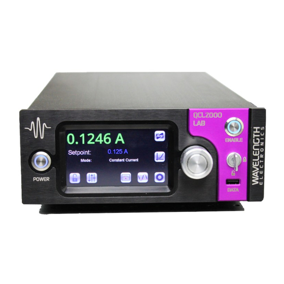
VIRTUAL INSTRUMENT
Remote Control of LAB Series Instruments
REMOTE INSTRUMENT CONTROL
Wavelength's Virtual Instruments offer higher level remote
control based on the Command Set for these TMC class
instruments. See the
LAB Series Instrument Command Set
document for lower level control.
These free applications are executable files that use the
National Instruments Run Time Engine.
One of each type of instrument can be operated at a time.
If you would like different default values or functionality,
or the full VI, contact Technical Support. Custom Virtual
Instruments can easily be coded.
TABLE OF CONTENTS
COMPUTER SPECIFICATIONS
OPERATING INSTRUCTIONS - QC LAB
OPERATING INSTRUCTIONS - TC LAB
OPERATING INSTRUCTIONS - LDTC LAB
ADDITIONAL TECHNICAL INFORMATION
TROUBLESHOOTING
WARRANTY & CERTIFICATION
Windows Operating System Compatibility
Processor
RAM
Screen Resolution
Disk Space
Installation Prerequisites
406-587-4910
www.teamWavelength.com
QCL LAB, TC LAB, LDTC LAB
14
25
26
27
COMPUTER SPECIFICATIONS
COMPUTER SYSTEM REQUIREMENTS
Windows 10/8.1/8/7 SP1 (32- and 64-bit)
Windows Server 2012 R2 (64-bit)
Windows Server 2008 R2 SP1 (64-bit)
Pentium III/Celeron 866 MHz (or equivalent) or later (32-bit)
Pentium 4 G1 (or equivalent) or later (64-bit)
256 MB minimum
1024 x 768 pixels
5 GB available hard disk space (32-bit)
20 GB DirectX 9 graphics device with WDDM 1.0 or higher driver (64-bit)
NI LabVIEW
-OR-
NI Runtime Engine for 2015, SP1 - 32 bit (2017, 64 bit for LDTC LAB)
NI-VISA Device Drivers
Applies to Revision 1
© October 2019
1
2
6
®
e
Advertisement

Summary of Contents for Wavelength Electronics LAB Series
- Page 1 VIRTUAL INSTRUMENT Remote Control of LAB Series Instruments QCL LAB, TC LAB, LDTC LAB REMOTE INSTRUMENT CONTROL Wavelength's Virtual Instruments offer higher level remote control based on the Command Set for these TMC class instruments. See the LAB Series Instrument Command Set document for lower level control.
- Page 2 QCL Software Downloads page, click Stop: Use the Stop button to gracefully end the LabVIEW Interface for QCL LAB Series Instrument remote control of the instrument. Any commands and download it to the computer. in process are completed prior to ending remote control.
- Page 3 SETTINGS & MONITORS TAB MONITORS The Settings & Monitors tab is used as the main control for Actual QCL Current (A): Monitor output current, in Amps, to remote operation. the load. Power: The Power button functions the same as the front Actual QCL Voltage (V): Monitor output voltage, in Volts, to panel power switch on the instrument.
- Page 4 VI SCAN TAB Perform a VI characterization scan of the QCL load. Input scan settings, file name and location to store the scan data, and start or stop the scan. Current Start (A): In the Current Start control, type the current, in Amps, at which to start the VI scan.
- Page 5 DATA LOGGING TAB The chart display starts when the Virtual Instrument application starts. It displays the last 17 minutes of data. Interval (sec): In the Interval control, type the desired interval, in seconds, for data to be recorded. The range is 1 to 10 seconds. Log Data button: Click this button to start or stop logging output current and current limit data to a file.
- Page 6 TC Software Downloads page, It is NOT recommended to use this method of stopping click the LabVIEW Interface for the TC LAB Series and the application. Instead, use the STOP button. download it to the computer. Stop: Use the Stop button to gracefully end 2.
- Page 7 SETTINGS & MONITORS TAB The Settings & Monitors tab is used as the main control for remote operation. Figure 7. Settings & Monitors Tab Power: The Power button functions the same as the front Temp Limit Min (°C): In the Temp Limit Min control, type the panel power switch on the instrument.
- Page 8 INTELLITUNE SETTINGS ® IntelliTune Mode: Choose IntelliTune Mode. The TC LAB instrument will characterize the best PID parameters for your load based on this setting once the IntelliTune Start button is pressed if not in Manual Tune mode. • Manual Tune - IntelliTune will not run. •...
- Page 9 SENSOR TAB The Sensor tab is where the active sensor is chosen, custom sensors are created, or bias currents are adjusted. Figure 8. Sensor Tab Active Sensor: Shows the sensor that is currently selected Set as Active Sensor: Set the sensor profile selected with for use with the TC LAB instrument.
- Page 10 Calibration Coefficients: Depending on the choice of sensor, Custom Sensor Type: Choose a sensor type for custom different calibration options will appear. sensor configuration. A sensor name and parameters below must also be configured before the Create Custom Sensor • Thermistor (Steinhart-Hart) button is pushed.
- Page 11 TEMPERATURE SCAN TAB The Temperature Scan tab allows plotting and saving of temperature (actual and set) as a function of time, over a range of temperatures defined in the controls of this tab. Note that while the functionality of the Temperature Scan in the VI is the same as that on the front panel of the instrument, the commands to carry this scan out are different.
- Page 12 DATA LOGGING TAB The chart display starts when the Virtual Instrument application starts. It displays the last 17 minutes of data. Figure 13. Data Logging Tab Interval (sec): In the Interval control, type the desired interval, in Actual Temperature (°C): The actual temperature is shown in seconds, for data to be recorded.
- Page 13 ADDITIONAL SETUP TAB The Additional Setup tab is where profile names can be edited, added, and saved. Additionally, cable resistance, tolerance parameters, remote enable, and laser shutdown signal polarity are set on the Additional Setup tab. Figure 14. Additional Setup Tab Existing Profile Name: Click in the field to list all of the existing Tolerance Parameters: Sets parameters that will enable the profile names stored on the TC LAB instrument.
- Page 14 Software Downloads page, click the LabVIEW the user to set and monitor the status of the instrument Interface for LDTC LAB Series Instrument and download remotely. Figure 16 gives an example of the GUI. it to the computer. Numerical monitor-only values have a gray background, and are uneditable fields (for example, see Actual Temperature).
- Page 15 TEMPERATURE CONTROL TAB Figure 17. Temperature Control Tab ® TC ENABLE: Press this boolean control to enable or disable PARAMETERS NTELLI output current to the TEC. P: Sets the proportional gain term value. Range is 0.1-1000. I: Sets the integral term value. Range is 0-200. D: Sets the derivative term value.
- Page 16 TEMPERATURE SENSOR Temperature Sensor: Use this dropdown menu to select the sensor for temperature control. It is populated with all the available factory- and user-defined sensors. Bias Current: Use this dropdown menu to select the bias current for the temperature sensor. Options are Automatic, 10 μA, 100 μA, 1 mA, 10 mA.
- Page 17 LASER CONTROL TAB Figure 19. Laser Control Tab LDD ENABLE: Press this boolean control to enable or disable Laser Voltage (V): This indicator displays the voltage laser current. measured across the laser in Volts. Monitor Photodiode Current (A): This indicator displays the current, in Amps, measured through the photodiode.
- Page 18 PHOTODIODE CONFIGURATION PD Range: Select the operating range for the photodiode. The three options are 500 μA, 5 mA, 10 mA. Choose the range that optimizes the dynamic range of the photodiode. PD Transfer Function (W/mA): Set the transfer function that scales the photodiode current to power.
- Page 19 SETTINGS TAB Figure 21. Settings Tab CUSTOM SENSOR CONFIGURATION Save Configured Sensor: Press the SAVE button when the calibration parameters, the Sensor Name, and the Sensor Sensor Type: Use this dropdown menu to select the type Type have been properly filled out. Pressing SAVE will commit of sensor to create.
- Page 20 ERRORS Check Errors: Use this button to query the Error String of the instrument. When lit, the query is in process. You can also clear errors displayed on the instrument front panel by checking errors. Error String: This indicator displays the contents of the error queue when Check Errors is pressed.
- Page 21 SCANNING TAB Figure 22. Scanning Tab Preparing Temperature Scan: This indicator is lit when the TEMPERATURE SCAN Begin TC Scan button has been pressed, but the scan has Start Temperature: Input the temperature for the scan to not yet started. Some scans will take slightly longer to begin begin.
- Page 22 V/I SCAN V/I Scan should only be operated in Constant Current (CC) Mode. Start Current (A or mA): Input the laser current value for the scan to begin. Stop Current (A or mA): Input the laser current value for the scan to end.
- Page 23 DATA LOGGING TAB Figure 23. Data Logging Tab TEMPERATURE CONTROL LASER This plot shows various temperature control parameters as a This plot shows various laser control parameters as a function function of time. There are four parameters that populate the of time.
- Page 24 LDTC STATUS TAB Figure 24. LDTC Status Tab TC STATUS LD STATUS Laser Type & Control Mode: There will be two indicators lit Temperature Units: The indicator corresponding to the currently active temperature units will be lit. in this cluster, one of either Laser Type A/B or Laser Type C, and one of either Constant Current (CC) or Constant Power Bias Current: There will be two indicators lit in this cluster, one (CP), indicating the laser type and operation mode currently...
- Page 25 QCL/TC/LDTC LAB LabVIEW Interface hardware from Wavelength Electronics, and may not be rebranded or resold under any other name. Wavelength Electronics makes no claims as to the fitness of this software for use in any specific application.
- Page 26 TROUBLESHOOTING PROBLEM POTENTIAL CAUSE SOLUTION My instrument does not appear in the The instrument is not connected to the • Check the power cables to make Choose Instrument / Device ID menu. computer properly or the power is not on. sure they are attached properly and securely, and the rear power switch is turned on.
- Page 27 As a general policy, Wavelength Electronics, Inc. does not the United States National Institute of Standards and Technology, to recommend the use of any of its products in life support applications the extent allowed by that organization’s calibration facilities, and to...
Need help?
Do you have a question about the LAB Series and is the answer not in the manual?
Questions and answers