Table of Contents
Advertisement
Quick Links
7305-14 4W-4W/2W Prescription Line Amplifier SF to E&M
Module and 7305-19 4W-4W/2W Prescription Line
Amplifier SF to E& M W/Loopback Module
CONTENTS
. . . . . . . . . . . . . . . . . . . . . . . . . . . . . . . . . . . . . . . . . . . . . . . . . . . . . . . . . . . . . . . . . . . . . . . . . . . . .
. . . . . . . . . . . . . . . . . . . . . . . . . . . . . . . . . . . . . . . . . . . . . . . . . . . . . . . . . . . . . . . . . . . . . . . . . . . . .
. . . . . . . . . . . . . . . . . . . . . . . . . . . . . . . . . . . . . . . . . . . . . . . . . . . . . . . . . . . . . . . . . . . . . . . . . . . . .
e1999 Charles Industries Ltd.
CLEI is a trademark of Bell Communications Research, Inc.
All rights reserved. Printed in United States of America.
The availability of features and technical specifications herein subject to change without notice.
Telecommunications Group
. . . . . . . . . . . . . . . . . . . . . . . . . . . . . . . . . . . . . . . . . . . . . . . . . . . . . . . . . . . . . . . . . . . . . . . . . . .
. . . . . . . . . . . . . . . . . . . . . . . . . . . . . . . . . . . . . . . . . . . . . . . . . . . . . . . . . . . . .
. . . . . . . . . . . . . . . . . . . . . . . . . . . . . . . . . . . . . . . . . . . . . . . . . . . . . . . . . . . . . . . . .
. . . . . . . . . . . . . . . . . . . . . . . . . . . . . . . . . . . . . . . . . . . . . . . . . . . . . . . . . . . . . . . . . . . . . . . . . . .
. . . . . . . . . . . . . . . . . . . . . . . . . . . . . . . . . . . . . . . . . . . . . . . . . . . . . . . . . . . .
. . . . . . . . . . . . . . . . . . . . . . . . . . . . . . . . . . . . . . . . . . . . . . . . . . . . . . . . . . . . . . . . . . . . . . . . . .
. . . . . . . . . . . . . . . . . . . . . . . . . . . . . . . . . . . . . . . . . . . . . . . . . . . . . . . . . . . . .
. . . . . . . . . . . . . . . . . . . . . . . . . . . . . . . . . . . . . . . . . . . . . . . . . . . . . . . . . . . . . . . . . . . . .
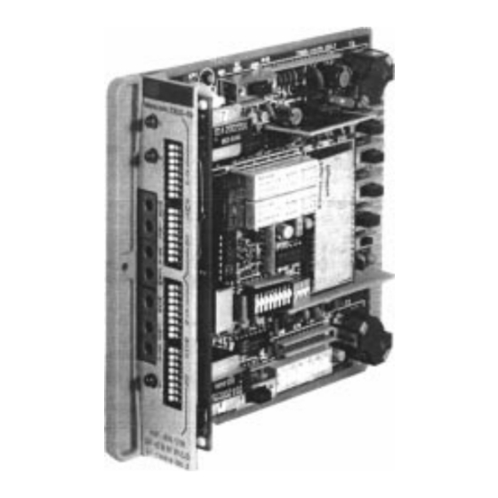
Figure 1. 7305-19 4W-4W/2W SF To E&M W/LBK Module
. . . . . . . . . . . . . . . . . . . . . . . . . . . . . . . . . . . . . . . . . . . . . . . . . . .
Section 730-514-202
Equipment Issue 2
Second Printing, December 1999
PAGE
2
3
3
3
10
10
11
15
17
18
18
20
Page 1 of 22
Advertisement
Table of Contents

Summary of Contents for Charles 7305–14 4W–4W
-
Page 1: Table Of Contents
..............Figure 1. 7305–19 4W–4W/2W SF To E&M W/LBK Module e1999 Charles Industries Ltd. CLEI is a trademark of Bell Communications Research, Inc. -
Page 2: Part 1. General
Section 730–514–202 GENERAL Document Purpose This document provides general, installation, alignment and testing information for the 7305–14 and 7305–19 4W–4W/2W Prescription Line Amplifier SF to E&M modules. Document Status This document is reprinted to provide a general editorial update. Equipment Function The 7305–14 and 7305–19 4W–4W/2W Prescription Line Amplifier SF to E&M are 400-type plug-in combined function modules (CFMs). -
Page 3: Part 2. Inspection
Equipment Identification Charles Industries’ equipment is identified by a model and issue number imprinted on the front panel or located elsewhere on the equipment. Each time a major engineering design change is made on the equipment, the issue number is advanced by 1 and imprinted on subsequent units manufactured. - Page 4 Section 730–514–202 Receive Voice Path The receive voice path of the CFMs is transformer coupled to the RCV LINE and provides a 150, 600 or 1200 ohm terminating impedance toward the facility. The receive voice path contains a gain stage (RCV GN) providing up to 24dB of gain in 0.1dB steps.
- Page 5 Section 730-514-202 Figure 5. Typical 4W–4W Application For 7305–14/19...
- Page 6 Section 730–514–202 Figure 6. Typical 2W–4W Application For 7305–14/19...
- Page 7 Section 730-514-202 Figure 7. 7305–14 4W–4W/2W SF To E&M (Issue 2) Block Diagram...
- Page 8 Section 730–514–202 Figure 8. 7305–19 4W–4W/2W SF To E&M W/LBK (Issue 2) Block Diagram...
- Page 9 Section 730-514-202 The + 7TLP output of the RCV GN is routed to the RCV EQLR (receive equalizer) which provides amplitude equalization for loaded and nonloaded cable facilities. The output of the RCV EQLR is applied to the SF RECEIV- ER and the RCV ATN (receiver attenuator) thru the RCV FET switch.
-
Page 10: Part 5. Mounting
Section 730–514–202 Power Supply The on-board REGULATED POWER SUPPLY derives the necessary voltages to operate the CFMs from a –48VDC (nominal) source and power return ground applied at pins 35 and 17 respectively. 2713Hz Tone Activated Loopback (7305–19 Only) The 7305–19 provides tone-operated loopback toward the 4W facility. A continuous 2713Hz loopback control sig- nal applied to the RCV LINE for a minimum of 2 seconds satisfies the first condition for loopback operation. -
Page 11: Part 7. Options
Section 730-514-202 Lead Designation RCV LINE XMT LINE XMT LINE SX RCV LINE SX 9, 11 E & M SIGNALING LEADS 39, 23 37, 19 36, 21 34, 1 7305–19 ONLY –48 V SPARE PINS OPTIONS The CFMs are equipped with DIP switches, slide switches and a screw option that are used to condition the mod- ules for proper application and operation. - Page 12 Section 730–514–202 Front Panel RCV and XMT GN/ATN Switches(Transmission Level Adjustment) The RCV GN, ATN DIP switches and the XMT GN, ATN DIP switches are used to provide up to 24dB of prescrip- tion gain or attenuation in 0.1dB increments. See Part 8 for alignment of the receive and transmit voice paths. Switch S7 [BON (Build-Out-Network)] Switch S7 is used to balance out the DC resistance and capacitance of a 2W cable.
- Page 13 Section 730-514-202 7. Set switches on S8 as follows: 1, 2, 4 and –1 to IN; and 4’ and –.5 to OUT. Note: When no equalization is required or a flat frequency response of the receive amplifier is desired, place all switches on S8 to OUT.
- Page 14 Section 730–514–202 Switch Designation Switch Function Switch Position 7305–19 only S101 GAIN/ATN and S101 provides loopback gain or attenuation: S102 provides up to See Table 4 S102 level 24 dB, in 0.1 dB steps, for loopback level adjustment. S103 loopback control Disable tone detector (DTD) S103–1 IN Manual loopback (MLB) S103–2 IN...
-
Page 15: Part 8. Alignment
Section 730-514-202 Table 6. Loaded/Nonloaded Cable Equalization S8 Switches ’IN” (X) Equalizer Gain S8 Switches ’IN’ (X) Equalizer Gain Slope LF EQ 2800 400 Hz Slope LF EQ 2800 400 Hz 4’ –.5 –1 4’ –.5 –1 –0.4 +6.0 –2.5 +0.2 –0.9 +6.1... - Page 16 Note: If TMS or VFO connecting cords are terminated in Type 310 plugs, they can be adapted for connecting into bantam jacks by attaching a Charles Type 310 to Bantam Jack Adapter (14 inch) (p.n. 003-210367). One open bantam plug.
-
Page 17: Part 9. Testing
Section 730-514-202 Transmit Alignment Procedure Use the following steps to perform the transmit alignment procedure. Step Action Condition the local VFO to apply a 1000 Hz test tone at the required level and impedance specified on the CLR. Connect the VFO to the XMT STA jack on the front panel of the CFM. Arrange the TMS for terminated measurement specified on the CLR. -
Page 18: Part 10. Technical Assistance
11.1 Warranty Charles Industries, Ltd. offers an industry-leading, 5-year warranty on products manufactured by Charles Indus- tries. Contact your local Sales Representative at the address or telephone numbers below for warranty details. The warranty provisions are subject to change without notice. The terms and conditions applicable to any specific... - Page 19 Charles Industries, Ltd. offers a standard repair or exchange service for units either in- or out-of-warranty. With this service, units may be shipped to Charles Industries for either repair and quality testing or exchanged for a replacement unit, as determined by Charles Industries. Follow the Repair Service Procedure below to return units and to secure a repair or replacement.
-
Page 20: Part 12. Specifications
Section 730–514–202 SPECIFICATIONS The electrical and physical characteristics of the CFMs are as follows: 12.1 Electrical 12.1.1. Power Requirements (a) Voltage Range: –42.5 to –56./VDC. (b) Maximum Current Requirements: Idle: 50mA(7305–14); 75mA(7305–19). Busy: 70mA plus M lead current (7305–14); 95mA plus M lead current (7305–19). Loopback: 130mA (7305–19 only). - Page 21 Section 730-514-202 (e) RECEIVE PATH FILTER TIMINGS: Insertion time 13 +/–7msec; filter removal for SF tone shorter than 175 +/–60msec is 180 +/–70msec; filter removal for SF tones longer than 175 +/–60msec is 50 +/–10msec. (f) GUARD CIRCUIT TRANSITION TIMING: Enable time, 50+/–10msec; disable time, 225 +/–60msec. (g) SF TONE DETECTION BANDWIDTH: Will detect within 2600 +/–15Hz;...
- Page 22 Section 730–514–202 12.2 Physical See Table 7 for the physical characteristics of the units. Table 7. Physical Specifications Feature U.S. Metric Height 5.6 inches 14.2 centimeters Width 1.4 inches 3.5 centimeters Depth 6.0 inches 15.2 centimeters Weight (nominal) 15 ounces 425 grams Temperature 32_ to 120_F...
Need help?
Do you have a question about the 7305–14 4W–4W and is the answer not in the manual?
Questions and answers