Table of Contents
Advertisement
Quick Links
RED LION CONTROLS
INTERNATIONAL HEADQUARTERS
20 Willow Springs Circle, York, Pa. 17402, (717) 767-6511
Web site- http://www.redlion-controls.com
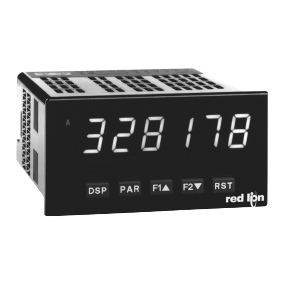
MODEL PAXC-1/8 DIN COUNTER PANEL METER
GENERAL DESCRIPTION
The PAXC (PAX Counter Panel Meter) offers many features and
performance capabilities to suit a wide range of industrial applications. The
optional Plug-in Setpoint Alarm Cards allow the opportunity to configure the
meter for alarms if that is a requirement.
The PAXC meter accepts digital inputs from a variety of sources including
switch contacts, outputs from CMOS or TTL circuits and all standard RLC
sensors. The meter can accept directional, uni-directional or Quadrature signals
simultaneously. The maximum input signal varies up to 34 KHz depending on
the count mode function configurations programmed. Each input signal can be
independently scaled to various process values.
The meter provides three different display indications. These include Counter
A, Counter B, and Counter C. Counter A and Counter B indicate the
corresponding input count value. Counter C indicates the sum or difference
between Counter A and Counter B values. Annunciators indicate which display
is being shown.
The front panel keys and three user inputs are programmable to perform
various meter functions. One function includes exchanging parameter lists,
allowing double the number of programmable setpoint, scale factor and count
load values.
The meter can have up to four setpoint outputs, determined by the Plug-in
cards. The Plug-in cards provide dual FORM-C relays (5 A), quad FORM-A
relays (3 A) or either quad sinking or quad sourcing open collector logic
outputs. The outputs can be assigned to any of the three displays. The outputs
can also be independently configured to suit a variety of control and alarm
requirements.
DIMENSIONS "In inches (mm)"
RED LION CONTROLS (UK)
Tapton Park, Chesterfield, Derbyshire S41 OTZ
ENGLAND
+44 1246 222122 FAX: +44 1246 221222
!
6-DIGIT LED DISPLAY (Alternating 8 digits for counting)
!
DUAL COUNT QUAD INPUTS
!
UP TO 3 COUNT DISPLAYS
!
PROGRAMMABLE SCALE FACTORS
!
PROGRAMMABLE FUNCTION KEYS / USER INPUTS
!
FOUR SETPOINT ALARM OUTPUTS (W/Plug-in card)
!
NEMA 4X/IP65 SEALED FRONT BEZEL
Once the meter has been initially configured, the parameter list may be
locked out from further modification entirely or setpoint, scale factor and count
load values can be made accessible. This lockout is possible through a security
code or user input.
The meter has been specifically designed for harsh industrial environments.
With a NEMA 4X/IP65 sealed bezel and extensive testing to meet CE
requirements, the meter provides a tough yet reliable application solution.
SAFETY SUMMARY
All safety related regulations, local codes and instructions that appear in this
literature or on equipment must be observed to ensure personal safety and to
prevent damage to either the instrument or equipment connected to it. If
equipment is used in a manner not specified by the manufacturer, the protection
provided by the equipment may be impaired.
Do not use this meter to directly command motors, valves, or other actuators
not equipped with safeguards. To do so can be potentially harmful to persons or
equipment in the event of a fault to the unit.
instructions prior to installation
and operation of the unit.
Note: Recommended minimum clearance (behind the panel) for
mounting clip installation is 2.1" (53.4) H x 5.5" (140) W.
1
CAUTION: Read complete
BULLETIN NO. PAXC-X
DRAWING NO. LP0510
EFFECTIVE 3/00
CAUTION: Risk of electric shock.
Advertisement
Table of Contents

Summary of Contents for RLC PAXC-1/8
- Page 1 The PAXC meter accepts digital inputs from a variety of sources including requirements, the meter provides a tough yet reliable application solution. switch contacts, outputs from CMOS or TTL circuits and all standard RLC sensors. The meter can accept directional, uni-directional or Quadrature signals SAFETY SUMMARY simultaneously.
-
Page 2: Specifications
Part I DIP switch selectable to accept pulses from a variety of sources including switch ELECTROMAGNETIC COMPATIBILITY contacts, outputs from CMOS or TTL circuits, and all standard RLC sensors. LOGIC: Input trigger levels V = 1.5 V max.; V = 3.75 V min. -
Page 3: Ordering Information
ORDERING INFORMATION TYPE MODEL NO. DESCRIPTION PART NUMBERS Counter Panel Meter, Upgradeable, AC Powered PAXC0000 Meter PAXC Counter Panel Meter, Upgradeable, DC/24 VAC Powered PAXC0010 Dual Setpoint Relay Output Card PAXCDS10 Optional Quad Setpoint Relay Output Card PAXCDS20 Plug-In PAXCDS Quad Setpoint Sinking Open Collector Output Card PAXCDS30 Cards... -
Page 4: Setting The Jumper And Dip Switches
2.0 SETTING THE JUMPER AND DIP SWITCHES To access the jumper and switches, remove the meter base from the meter Warning: Exposed line voltage exists on the circuit boards. Remove case by firmly squeezing and pulling back on the side rear finger tabs. This all power to the meter and load circuits before accessing inside of the meter. -
Page 5: Wiring The Meter
Cable length, routing, and shield termination are very important Ferrite Suppression Cores for signal and control cables: Fair-Rite # 0443167251 (RLC# FCOR0000) and can mean the difference between a successful or troublesome installation. Listed below are some EMC guidelines for successful installation in an TDK # ZCAT3035-1330A industrial environment. -
Page 6: Input Wiring
4.3 INPUT WIRING CAUTION: Sensor input common is NOT isolated from user input common. In order to preserve the safety of the meter application, the sensor input common must be suitably isolated from hazardous live earth referenced voltage; or input common must be at protective earth ground potential. If not, hazardous voltage may be present at the User Inputs and User Input Common terminals. -
Page 7: Reviewing The Front Buttons And Display
5.0 REVIEWING THE FRONT BUTTONS AND DISPLAY DISPLAY MODE OPERATION PROGRAMMING MODE OPERATION Index display through Counters (A, B, C). Quit programming and return to Display Mode Access Programming Mode Store selected parameter and index to next parameter " Function key 1; hold for 3 seconds for Second Function 1 ** Increment selected parameter value or selections Function key 2;... -
Page 8: Parameter Menu
PROGRAMMING TIPS ALTERNATING SELECTION DISPLAY It is recommended to start with Module 1. If lost or confused while In the explanation of the modules, the following dual display with arrows will programming, press the DSP key and start over. When programming is appear. - Page 9 COUNTER B OPERATING MODE COUNTER B RESET POWER-UP * " , .78. " , #*$ NONE dcntud dquAd1 <(& dquAd2 cnt2 dctud2 Counter B may be programmed to reset at each meter power-up. Select the operating mode for Counter B. SELECTION MODE DESCRIPTION...
- Page 10 6.2 MODULE 2 - User Input and Front Panel Function Key Parameters ( >7"*# PARAMETER MENU ADVANCE DISPLAY Module 2 is the programming for rear terminal user inputs and front panel function keys. " " 8&%74 "4 Three rear terminal user inputs are individually programmable to perform specific meter control functions.
- Page 11 MAINTAINED (LEVEL) RESET AND INHIBIT DEACTIVATE SETPOINT MAINTAINED (LEVEL) " " " " 8&%74 "4 8&%74 "4 #$%&$' #$%&$' &.%&$' &.%&$' The meter performs a reset and inhibits the displays configured as <(& , as The meter deactivates the setpoints configured as <(&...
- Page 12 6.3 MODULE 3 - Display and Program Lock-out Parameters ( ?7'!# PARAMETER MENU x = Counter A , Counter B, and then Counter C n = Setpoints 1 to 4 Module 3 is the programming for Display lock-out and “Full” and “Quick” COUNT LOAD A B C ACCESS LOCK-OUT * Program lock-out.
- Page 13 6.4 MODULE 5 - Counter C Input Parameters ( 57#$%# PARAMETER MENU Module 5 is the programming for Counter C. For maximum input frequency, the counter operating mode should be set to *!*( when not in use. When set to COUNTER C SCALE FACTOR *!*( the remaining related parameters are not accessible.
- Page 14 6.5 MODULE 6 - Setpoint (Alarm) Parameters ( B7&.$ PARAMETER MENU SETPOINT ANNUNCIATORS* Module 6 is the programming for the setpoint (alarms) output parameters. To " have setpoint outputs, a setpoint Plug-in card needs to be installed into the ')$72 PAXC (see Ordering Information).
- Page 15 SETPOINT ASSIGNMENT COUNTER AUTO RESET * " " 38$!72 3&*72 ZErOAS CLdAS 3 #*$ , #*$ # #*$ 3 #*$ ZErOAE CLdAE This automatically resets the display value of the Setpoint Assignment ( 3&*7 Select the display that the setpoint is to be assigned. ) counter each time the setpoint value is reached.
-
Page 16: Troubleshooting
6.6 MODULE 9 - Factory Service Operations ( ;7"#& RESTORE FACTORY DEFAULTS PARAMETER MENU " #!-( Use the arrow keys to display #!-( BB and press PAR. The meter will display %(&($ and then returns to #!-( 56 . Press the DSP key to return to the Display Mode. - Page 17 The customer agrees to hold Red Lion Controls harmless from, defend, and indemnify RLC against damages, claims, and expenses arising out of subsequent sales of RLC products or products containing components manufactured by...
-
Page 18: User Inputs
F1/F2 Keys 47)*. %(&($ -(#.$ &#"3# '% #*$'- .78. Counter x Counter x Counter x Counter x Counter x Counter x Counter x Operating Reset Decimal Scale Scale Count Load Reset at Mode Action Position Factor Multiplier Value Power-up >7"*# 8&%74 8&%7>... - Page 19 This page intentionally left blank.
- Page 20 RED LION INTERNATIONAL HEADQUARTERS 20 Willow Springs Circle, York, Pa. 17402 (717) 767-6511 FAX: (717) 764-0839 CONTROLS Web site- http://www.redlion-controls.com E-mail- sales@redlion-controls.com RED LION CONTROLS (UK) Tapton Park, Chesterfield, Derbyshire S41 OTZ ENGLAND +44 1246 222122 FAX: +44 1246 221222...
Need help?
Do you have a question about the PAXC-1/8 and is the answer not in the manual?
Questions and answers