
Summary of Contents for STS DL/N 64 Series
- Page 1 Operating Manual Datalogger, Program and Accessories Operating Manual DEB004H Seite 1 von 68 14. März 2006...
-
Page 2: Table Of Contents
Operating Manual TABLE OF CONTENTS Introduction ........................4 1.1. Getting started ......................4 1.1.1. Unpacking ......................4 1.1.2. Installation......................4 Program Installation......................5 2.1. System Requirements....................5 2.2. Program Installation .....................5 2.3. Connecting Datalogger, DL/N series 64 ................9 2.4. Connecting Datalogger, DL/N series 70 ................9 General Software Functions ...................10 3.1. - Page 3 Reset Conductivity Parameters to Factory Settings ...........64 Dataconversion Program....................65 Notes ..........................67 General Information ......................68 10.1. Requirements / Fundamentals ..................68 10.2. Abbreviations ......................68 10.3. STS Companies......................68 Valid for release from V 2.12 Created on: 14.03.2006 Replaces version created on: Status: DEB004H Seite 3 von 68...
-
Page 4: Introduction
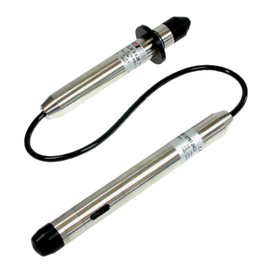
Operating Manual 1. Introduction The datalogger DL/N is suitable for continuous monitoring of ground- and surface water. Three measuring systems are integrated (some as option) to monitor conductivity, temperature and pressure or level. The conductivity gives you information about the solved salt content of the water (pollution of water). -
Page 5: Program Installation
Operating Manual 2. Program Installation 2.1. System Requirements Hardware requirements: • IBM compatible PC or Laptop Processor min. 200 MHz, available harddisc space min. 50 MByte, memory (RAM) min. 64 MByte • Operating system Windows 98 / 98SE / Me / NT from version 4 (min. Service Pack 6 and Internet Explorer from Version 6.0) / 2000 / XP •... - Page 6 Operating Manual The InstallShield Wizard starts: Choose destination folder for the installation: DEB004H Seite 6 von 68 14. März 2006...
- Page 7 Operating Manual Specify the destination paths for user-data, configuration-data and measured-data: Ready to install the program: DEB004H Seite 7 von 68 14. März 2006...
- Page 8 Operating Manual Mark “Launch DL/N 70” and click on “Finish” to start the program immediately: The program can also be started via the Start Menu: DEB004H Seite 8 von 68 14. März 2006...
-
Page 9: Connecting Datalogger, Dl/N Series 64
Operating Manual 2.3. Connecting Datalogger, DL/N series 64 • Remove the cover / screw-on cap from the Datalogger. • Connect the interface cable to an available port on your PC. • Cable connection: Connect the interface cable to the Datalogger. •... -
Page 10: General Software Functions
Operating Manual 3. General Software Functions 3.1. General Notes Additional information appears by positioning the mouse pointer over a button. Mouse pointer 3.2. Connection Window Starting the datalogger program, the connection window to select the port (COM1 to COM8), the baudrate (default: 38400 bps, only for DL/N, series 70) and the language appears. -
Page 11: Offline Operation
Operating Manual 3.2.1. Offline Operation “File open” (Offline-Mode) opens the window “load data”. You can load a previous saved data file from the PC. The data can be viewed by clicking the graphic button (see chapter 4.2). 3.2.2. Connect “Connect” starts the main window. If a communication error occurs, following message appears: By clicking “Repeat”, another attempt to connect will be made, clicking „Cancel“... -
Page 12: Menu
Operating Manual 3.3. Menu 3.3.1. File 3.3.1.1. Read in Data The “File open” menu item is only active if the Datalogger program is in “Offline” - mode. Entering the “Offline” – mode: 1. Start the software. The connection window appears. Press the “File Open” – button. 2. - Page 13 Operating Manual 3.3.2.1. Datalogger settings The menu item “Company data” shows the following window. The entered data appears in the printout (see chapter 4.2 “Data View”). 3.3.2.2. Save configuration With this function all important settings (see chapter 3.3.2.3) can be stored into a file. With this file the identical settings can be loaded into another Datalogger.
-
Page 14: Menu
Operating Manual In the menu „Extras...“, different variations of the filename can be created. This arrangement of different file names appears automatically in the save dialog. Three fixed or one customer specific filename are selectable. The user defined filename can be composed from different information like free text but also from code like date, identification or serial number. -
Page 15: Main Window
Operating Manual 3.4. Main Window All important functions can be selected in the main window. The latest relevant data is being displayed in the statusbar. 11 12 Menu Clock/date adjustment Operating switch Pressure indicator Display operating mode Estimated battery lifetime Data transfer Temperature indicator (Option) Data view... - Page 16 Operating Manual TIMER: Logging starts at the time “Start” and stops only when the operating switch is manually switched off. If the checkbox “Stop” is activated, the datalogger starts at the time “Start” and stops at the time “Stop” automatically. For timer operation, the switch must be in position „TIMER“...
-
Page 17: Further Software Functions Dl/N, Series 64
Operating Manual 4. Further Software Functions DL/N, series 64 4.1. Data Transfer In the “Data Transfer” window data can be uploaded to the PC from the Datalogger. The upper portion of the window displays status information. If no measured value was outside the predefined limit values (set in “Configure Datalogger”-dialog chapter 4.4) during the last measurement series, the message “The limit values were not exceeded”... - Page 18 Operating Manual All the data stored in the Datalogger will be read out. The data transfer will stop once the data has been successfully transferred, a connection error occurs or the stop-button has been pressed. If neither a start nor an end time and date is being set, all the stored data will be read out. If only the start time and date is being set, the program will read out all the data starting at the start time and date until the present.
-
Page 19: Data View
Operating Manual 4.2. Data View The Data View allows to analyse and print out the measured data which has been read out. The Info bar shows the name (see chapter 4.4 ), the serial and transducer numbers of the DL. 1 2 3 4 5 Changes back to the normal view (1:1) after the zoom view. - Page 20 Operating Manual Enabling “Graphic” resp. “Table” switches between the graphical and the tabular display. Turns the “Print” or “Temperature” or “Counter” charts on or off in the image. Date and time of the first and last measurement values read out. Also the total quantity of measurement data read out is being shown.
-
Page 21: Save Dialog Box
Operating Manual 4.3. Save Dialog Box This function is only active if data were transferred from the datalogger. The data can be stored as ASCII- or XML files. The default file name is according to the settings made in the menu “Extras”, see chapter 3.3.2.5. Example of ASCII file: Example of XML file: DEB004H... -
Page 22: Datalogger Configuration
Operating Manual 4.4. Datalogger Configuration Menu for the datalogger configuration. Recording of: pressure, temperature, counter, pressure and temperature or pressure and counter Storage rate: specifies the rhythm in which the data is being stored. The storage rate must be an integer multiple of the sample rate. Storage mode: Storage rate = Sample rate: Storage rate is equal to sample rate... - Page 23 Operating Manual Upper limit value Lower limit value Activating the display of limit values: The DL uses symbols to display whether the pressure measured in the last measurement series has underrun or overrun the predefined range. The range is defined by the upper and lower limit value. The “Data Transfer” window will also display if a limit value has been exceeded.
- Page 24 Operating Manual Below: The DL does not start recording data until the pressure drops below the specified value. Recording will stop if the pressure exceeds the specified value and does not drop below it again during the time it takes for the memory page to be filled. The DL does not start recording data again until the pressure drops below the specified value.
-
Page 25: Taring
Operating Manual 4.5. Taring 4.5.1. Level Measurement The measured value is multiplied by the scaling factor. This factor must be between 0.3 and 2.0. Value for the density of the measuring medium. This box is only active if the DL has been synchronized in a “length unit”... - Page 26 Operating Manual Displays the stored value (adjusted by the scaling or density factor as well as the taring or the depth to water value). Depth to water value: Distance between ground and water surface. This value has to be entered in the calibrated unit of the Datalogger. This value can be up to +/- 3200 with the number of decimal places with which the Datalogger has been calibrated (evidently in the main window).
-
Page 27: Pressure Measurement
Operating Manual 4.5.2. Pressure Measurement Measured value: This is the effectively measured value, without consideration of taring, depth to water, scaling or density. If the measured depth (location of the sensor membrane) is not equal to the effective depth, the measured value can be corrected to the effective value in the calibrated unit of the Datalogger. -
Page 28: Info
Operating Manual 4.5.3. Info Symbolic block diagram of the Datalogger. Measured value: This is the effectively measured value, without consideration of taring, depth to water, scaling or density. Displays the stored value (adjusted by the scaling or density factor as well as the taring or the depth to water value). -
Page 29: Synchronize Time
Operating Manual 4.6. Synchronize Time PC – register: shows the actual PC- time and date. Manual – register: Fields to enter time and date manually. Current PC – time Current Datalogger - time Apply the PC – time/date or the manually entered time/date to the Datalogger. 4.7. -
Page 30: Further Software Functions Dl/N, Series 70
Operating Manual 5. Further Software Functions DL/N, series 70 5.1. Menu “File” This function allows to create a log-file which contains information about the internal setup of the datalogger. The file created by this function can help to analyse the situation in case of problems. It is not a file which is useful directly for the datalogger user. -
Page 31: Conductivity Recalibration
Operating Manual 5.2.2. Conductivity Recalibration... The cleaning and recalibration process of the conductivity module is described in chapter 7.3. 5.2.3. Change Baudrate… The baudrate is set on 38400 bps ex works. To communicate later over a communication module, the baudrate must be changed to 9600 bps. 5.2.4. -
Page 32: Data Transfer
Operating Manual 5.2.6. Data Transfer With „Transfer of the measuring data“, the data can be read out of the datalogger into the PC. The actual read out status is shown in the upper field. These are the recorded measured data, date and time of the first and last measuring value and the number of read out values. - Page 33 Operating Manual Reading out the data from the last measurement series (i.e. since the data recording function was last started). Press the button again, the datalogger will read out the second-last measurement series in addition etc. The data transfer will stop once the data has been successfully transferred, a connection error occurs or the stop-button has been pressed.
- Page 34 Operating Manual Stops / interrupts the data transfer. All the data read out until this button was pressed will be transferred. This function allows to delete ALL the recorded data in the datalogger. To do this, a password must be entered (see also chapter 3.3).
-
Page 35: View Data
Operating Manual 5.2.7. View Data “Data View” allows to analyse and print out the measured data which has been read out. The info bar shows the name (see chapter 5.2.9.1), the serial and transducer numbers of the DL. 1 2 3 4 5 Changes back to the normal view (1:1) after the zoom view. - Page 36 Operating Manual Change colour: To enhance the quality of the printout on a black and white printer, the image can be changed to black and white. One tab is to show the data in graphical form, the tab “Table” shows the values in a table form.
-
Page 37: Save Dialog Box
Operating Manual 5.2.8. Save Dialog Box This function is active only if data were transferred from the datalogger. The data can be stored as ASCII- or XML files. The default file name is according to the settings made in the menu “Extras”, see chapter 3.3. Example of ASCII file: Example of XML file: DEB004H... -
Page 38: Datalogger Configuration
Operating Manual 5.2.9. Datalogger Configuration Menu for the datalogger configuration. 5.2.9.1. Tab „Record“ Record type selection: These checkboxes are to select the recording measurands. “Temperature”, “Conductivity” and “Counter” are only available if the respective option in the datalogger is activated. With “Conductivity”... - Page 39 Operating Manual Storage mode: Ring memory: As soon as the datalogger memory is full, the oldest data will be overwritten by the new data. Stopmode: As soon as the datalogger memory is full, recording stops. If the memory is already full when starting the datalogger, following message appears: The datalogger can be restarted only if the memory is erased according to chapter 5.2.6.
- Page 40 Operating Manual 5.2.9.2. Tab „Operating Mode“ Mode: Selectable operating mode: Standard With threshold recording (Option) Threshold dependent storage interval (Option) Time dependent storage interval (Option) The lower window area depends on the selected mode (see following description). DEB004H Seite 40 von 68 14.
- Page 41 Operating Manual Mode „Standard“ (A) Storage interval 1 Storage mode: Storage rate = Sample rate: Storage rate is equal to sample rate Mean value: The arithmetical mean value will be stored Minimum value: The lowest value of the measrow will be stored Maximum value: The highest value of the measrow will be stored 2 Storage rate:...
- Page 42 Operating Manual Mode „With threshold recording“ (B) 1 Storage interval: see mode „Standard“ 2 Threshold values for channel: Pressure: The values of pressure are considered Temperature: The values of the temperature are considered 3 Upper: The DL does not start recording data until the pressure exceeds the specified value. Recording will stop if the pressure drops below the specified value.
- Page 43 Operating Manual 3 Inner: The DL does not start recording data until the pressure is between the specified values. Recording will stop if the pressure is outside the specified range. The DL starts recording again if the pressure returns to the specified values. 3 Outer: The DL does not start recording data until the pressure leaves the specified range.
- Page 44 Operating Manual Mode „Threshold dependent storage interval“ (C) This mode changes the storage interval depending on the actual pressure or temperature. In this mode, the sample interval is equal to the storage interval. 1 Storage interval 1/2: Setting the storage interval 1 and 2 2 Threshold value(s) for channel: Pressure: The values of pressure are considered Temperature: The values of the temperature are considered...
- Page 45 Operating Manual Mode „Time dependent storage interval“ (D) This mode records data within a specific time window in two different storage intervals. The sample interval is equal to the storage interval. Period 1: During this time window, the “storage interval 1” will be used. Period 2: This time window will complete automatically the period 1 to a 24 h time period.
- Page 46 Operating Manual 5.2.9.3. Tab „Events“ Only active when the option event is activated in the datalogger Setting this flag activates the option “Events” if the datalogger is switch on. This function can be used if the datalogger is connected with a communication module and events have to be transmitted automatically.
- Page 47 Operating Manual The DL does not give an event until the pressure falls below the specified lower value. The upper and the lower value which can be entered correspond to the yellow marked field. A new event is only given if the event has been confimed by the datalogger software and if the pressure /temperature has exceeded the upper value.
- Page 48 Operating Manual “Level measuring“ to use the DL in a level application “Pressure measuring“, to use the DL in another application, see following chapter Tab „Info“ explains the difference between “measured value” and “stored value”. Displays the stored value (adjusted by the scale or density factor as well as the taring or the depth to water value).
- Page 49 Operating Manual Pressure measuring Measured value: This is the effective measured value, without consideration of tare, depth to water, scale or density. Default: Tare is deactivated Tare: Enter the actual desired value, click “Apply” Displays the stored value, adjusted by the scale or density factor as well as the tare. DEB004H Seite 49 von 68 14.
- Page 50 Operating Manual Info The info window explains the meaning of “Sample value” and “Storage value”. Symbolic block diagram of the datalogger. Measured value: This is the effective measured value, without consideration of tare, depth to water, scale or density. Displays the stored value, adjusted by the scale or density factor as well as the tare or depth to water value.
- Page 51 Operating Manual 5.2.9.5. Tab „Conductivity“ Only active when the channel conductivity is activated in the datalogger (option) The conductivity is very strongly temperature-dependent. The conductivity increases with increasing temperature (approx. 2 % per °K) at natural waters. It is therefore necessary to correct the measurements on a reference temperature (25 degrees celsius).
-
Page 52: Synchronize Time
Operating Manual Allowed range : 0.001 to 10’000 Unit of pulse: max. 10 characters text or numbers 5.2.10. Synchronize Time PC – register: shows the actual PC- time and date. Manual – register: Fields to enter time and date manually. Current PC –... -
Page 53: Battery Indicator
Operating Manual 5.2.11. Battery Indicator The battery indicator shows the calculated capacity of the battery. The less green fields appear, the lower the battery capacity is. It is advisable to change the battery before it is discharged completely. If the capacity of the battery falls below a certain level, the datalogger switches off automatically and following message appears: The data remains in the datalogger memory and can be read out after the battery has been changed. -
Page 54: Theoretical Calculation Of The Battery Life Time
Operating Manual 6. Theoretical calculation of the battery life time 6.1. DL/N, series 64 Precondition/acceptance for the calculation • The calculation is not valid for the display battery • For the calculation the storage interval and the sampling interval is equal •... -
Page 55: Dl/N, Series 70
Operating Manual • The stored data will not get lost during battery change • The self-discharge of the battery is approximately 4% per year at 25°C • The ambient temperature has a significant influence on the battery life time(see chart) •... -
Page 56: Maintenance
Operating Manual battery change • The self-discharge of the battery is approx. 1% per year at 20°C • The ambient temperature has a significant influence on the battery life time (see chart) • Current consumption DL (during measuring) approx. 3 – 5 mA •... -
Page 57: Battery Replacement Dl/N, Series 70
Operating Manual We recommend to mark the replaced batteries to make sure not using “old batteries” as new batteries by mistake. After replace the battery please set date and time of the datalogger again. 7.2. Battery Replacement DL/N, series 70 Open or close the datalogger The upper connector part with the thread (1) may not be turned against the lower part (2) when opening or closing the datalogger. -
Page 58: Maintenance Of The Conductivity Module
Operating Manual 7.3. Maintenance of the Conductivity module 7.3.1. Cleaning of the Conductivity module The necessary cleaning cycle depends on the quality of the medium the datalogger is used in. When using the datalogger in freshwater applications with good water quality checking and cleaning of the conductivity module is reduced to a minimum (seasonal or even annual checking). -
Page 59: Recalibration Of The Conductivity
Operating Manual 7.3.3. Recalibration of the Conductivity Please make sure to keep the datalogger AND the calibration liquid at least 6 hours in a room with approximately 20°C ambient temperature. The cleaning cycle of the conductivity module depends strongly on the quality of the medium, in which the DL is used. - Page 60 Operating Manual After cleaning the module under flowing water, clean it with destillated water. After cleaning with destillated water, dip the module into the recalibration liquid (standard of 1413 µS/cm). This liquid can be ordered from the supplier. Make sure to use always a standard liquid with 1413 µS/cm.
- Page 61 Operating Manual If the temperature change is bigger than 0.1°C/min. the recalibration process will be interrupted after 10 minutes even if the temperature is within 15 - 30°C. Only if the temperature change is ≤ 0.1°C/min. the recalibration process will proceed. Following message appears: DEB004H Seite 61 von 68...
- Page 62 Operating Manual Possible errors during the recalibration: If the temperature change is higher than 0.1°C/min: If the temperature of the calibration liquid is not within 15 to 30°C: If the conductivity module has not been cleaned properly, is damaged, or the calibration liquid is not clean anymore the calibration process will be interrupted: DEB004H Seite 62 von 68...
- Page 63 Operating Manual Interruption of the recalibration process by the user: After interrupting the recalibration process, the calibration values will not be lost, but will be set back to the factory settings automatically. If necessary restart the recalibration process. DEB004H Seite 63 von 68 14.
-
Page 64: Reset Conductivity Parameters To Factory Settings
Operating Manual 7.3.4. Reset Conductivity Parameters to Factory Settings The conductivity parameters can be reseted to factory settings. After reseting: DEB004H Seite 64 von 68 14. März 2006... -
Page 65: Dataconversion Program
Operating Manual 8. Dataconversion Program The data conversion program is installed with the datalogger program and can be started via “Start\Program\Dataconversion”. With this program the order of the data columns “Date, Time, Data (pressure+temperature)” can be changed. It is also possible to remove or add data columns again. Large data files can be splitted automatically into smaller ones which can be imported into Excel™. - Page 66 Operating Manual If the flag “split large files” is activated, files will be split in max. 3 files with approximately 60’000 measurement values to import it into Excel™. The filenames will be numbered as follows: e.g. example_1.con.txt, resp. example_2.con.txt or example_3.con.txt With the buttons “Description”, “Min-/Max-values”...
-
Page 67: Notes
Operating Manual 9. Notes __________________________________________________________________________________ __________________________________________________________________________________ __________________________________________________________________________________ __________________________________________________________________________________ __________________________________________________________________________________ __________________________________________________________________________________ __________________________________________________________________________________ __________________________________________________________________________________ __________________________________________________________________________________ __________________________________________________________________________________ __________________________________________________________________________________ __________________________________________________________________________________ __________________________________________________________________________________ __________________________________________________________________________________ __________________________________________________________________________________ __________________________________________________________________________________ __________________________________________________________________________________ __________________________________________________________________________________ __________________________________________________________________________________ __________________________________________________________________________________ __________________________________________________________________________________ __________________________________________________________________________________ __________________________________________________________________________________ DEB004H Seite 67 von 68 14. März 2006... -
Page 68: General Information
Personal Computer Transducer Universal Serial Bus Version xx 10.3. STS Companies Switzerland Italy STS Sensor Technik Sirnach AG STS Italia s.r.l. Rütihofstrasse 8 Via Gesu 5 CH – 8370 Sirnach I – 20090 Opera (MI) Tel. +41 (0)71 969 49 29 Tel.
Need help?
Do you have a question about the DL/N 64 Series and is the answer not in the manual?
Questions and answers