Table of Contents
Advertisement
Brown Manufacturing Group, Inc.
4661 Stafford SW
Wyoming, MI 49548
616-249-0200
www.brownmfg.net
customerservice@brownmfg.net
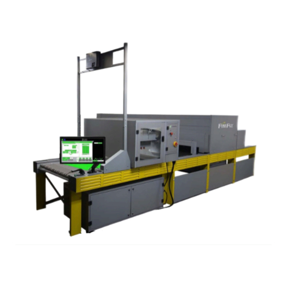
The Synergy™ Industrial Pretreat Module provides complete multi-variate control of
each garment. The system is designed for high volume digital decorators and connects
directly to the FireFly curing system, allowing for rapid evaporation of pretreat solution
and delivery to the digital output device.
$150.00
fax 616-249-3211
FireFly™ & Synergy™
FY2x36-45 & SY36-84
FireFly Curing System
Synergy Pretreat System
Instructions
US Patent# 10,011,136
April 2019
Advertisement
Table of Contents

Summary of Contents for BROWN FireFly FY2x36-45
- Page 1 FireFly™ & Synergy™ Brown Manufacturing Group, Inc. Instructions 4661 Stafford SW Wyoming, MI 49548 616-249-0200 fax 616-249-3211 US Patent# 10,011,136 www.brownmfg.net customerservice@brownmfg.net FY2x36-45 & SY36-84 FireFly Curing System Synergy Pretreat System The Synergy™ Industrial Pretreat Module provides complete multi-variate control of each garment.
- Page 2 Conveyor Dryer Brown Manufacturing Group, Inc. 4661 Stafford Ave. S.W. Setup Guide Wyoming, MI 49548 Phone: 616-249-0200 Fax: 616-249-3211 www.brownmfg.net customerservice@brownmfg.net...
- Page 3 Assembly A Firefly dryer consists of several modular assemblies BELT TRACKING which are joined together to create a complete conveyor ADJUSTMENT KNOBS dryer unit. Common modules are: TAKEUP ROLLERS OBJECT DETECT SENSORS BELT MOTORS LOAD DETECT SENSORS HEIGHT SENSORS BELT TRACKING KNOBS BELT ROLLERS SCANNER HOLDERS LEVELING FEET...
- Page 4 Consult your salesperson system is a modular system, your configuration may be for an engineering drawing of your particular system. different. Consult with Brown Manufacturing for the exact layout of your system. Clearance is required around the heat modules in order...
- Page 5 Assembly Step 3: Connect Modules: Assembly Step 5: Install Belts: Remove the cover grills from the frames of each section. Figure 11 First, loosen the Belt Tracking Knobs ( ) on Bolt each module to each adjoining module using the both the front and rear of the machine.
- Page 6 Due to the technical nature of these connections, it is recommended only a Brown Technician perform the final wiring operations. DISCONNECT SWITCH(ES) INPUT POWER CONNECTS HERE GROUNDING LUGS...
- Page 7 Machine Adjustments Belt Tension Apply enough tension to keep the belt from slipping on the roller. Excessive tension is unnecessary and may shorten the useful life of the belt. Belt Tracking Belt tracking is adjusted with the knobs on the end of the conveyor frame.
- Page 8 Brown Manufacturing Group, Inc. 4661 Stafford SW FireFly™ Wyoming, MI 49548 616-249-0200 fax 616-249-3211 Software www.brownmfg.net customerservice@brownmfg.net FF-3X27-30 Linx Control System Integration Innovation and the application of new technology are the keys to the new FireFly curing system. Step into the advanced world of BrownDigital and increase production rates exponentially while reducing floor space, power requirements and increasing operator control.
- Page 9 Your new FireFly curing system is equipped with a touch convection air movement in the upper air chamber. screen display that runs Brown Manufacturing Group, Inc. » CONVECTION BOTTOM: This is the percentage proprietary software that controls all the parameters of your speed of convection air in the bottom air chamber.
- Page 10 The Bottom Bar of the control panel displays the follow- ing information: » CURRENT TIME: The current time of day. : Press this button to access the MAINTE- » NANCE area. If a scheduled task has passed its due date, the icon will flash. : This button will access the SETTINGS menu.
- Page 11 Working with each control panel icon Any changes in the Middle Window parameters will cause DEFAULT this label to change to SAVE. If the new parameters need Pressing the DEFAULT button will bring you to the PRO- to be saved as a program, press SAVE. The PROGRAM GRAMS window.
- Page 12 TEMP CONVECTION TOP or BOTTOM The convection air fan recirculates air over top or from To change the set temperature, press the TEMP button. below the heaters and into the chamber. The speed of the The SET TEMPERATURE window will pop up. Use the fans is adjustable and that will adjust the amount of air that keypad to select a new temperature and then press the is moved.
- Page 13 BULB POWERS Each program stored within the FireFly can have specific bulb intensity levels. Select this icon and the Settings menu will appear. Pro- gramming these will be discussed in the section Setting Section. Figure 13: Set Bulb Intensity PRINT This button will print out the bar code label of the selected program to your label printer included in the Linx system.
- Page 14 Working with the Maintenance screen o LAST DATE PERFORMED: This pulls up a calendar. Select the correct date. o NEXT SCHEDULED DATE: This is calculated based on the FREQUENCY and the LAST DATE PERFORMED. o COMPLETED TASK TODAY: When the task is due, select the button and the calendar will reset to the current date and a new scheduled date will be calculated.
- Page 15 » PROGRAMS: This opens the list of stored pro- Figure 18: Settings window garment has tripped the height sensor. grams. » CALIBRATE TOUCH SCREEN: Contact Brown Manufacturing Group, Inc. if the touch screen is not viewing properly. » POWER MONITOR: The FireFly monitors the pow- er usage for the unit.
- Page 16 » RAW DATA: This is the lane information on speed » PROGRAM NAME: Select any program button and and temperature. that will replace the one currently running. Once pressed, the system will ask which prompt SELECT ZONE and then return to the HOME screen. SE- LECT ZONE is referring to which lane the program needs to run.
- Page 17 Conveyor Dryer Brown Manufacturing Group, Inc. 4661 Stafford Ave. S.W. Wyoming, MI 49548 Maintenance Guide Phone: 616-249-0200 Fax: 616-249-3211 www.brownmfg.net customerservice@brownmfg.net...
- Page 18 Recommended Weekly Maintenance: • Clean and Adjust Trip Sensor System • Clean and Adjust Load Sensor System • Clean Control Panel Fan Filters • Check Belt Tracking • Check Bulb Status Recommended Monthly Maintenance: • Check Camera Cooling Fan Filters •...
- Page 19 Check Bulb Status: 1) At each drone control panel press “Menu” 2) Press “Factory Setup” 3) Press “Test Bulbs” 4) Bulb test will report “Successful” if all bulbs are working correctly, or will identify those bulbs that are not working. Replacing a Bulb: Before replacing a bulb, it is important to determine that the bulb is, in fact, the problem.
- Page 20 expand bulb holders to allow bulbs to Check Camera Cooling Fan Filters: slide). Inspect camera cooling fan filters above main 9) Reverse steps to install new bulb. heat sections (Figure 6). Replace as necessary. Clean Blinders: 1) Remove camera access plate (Figure 6) 2) Clean lint &...
- Page 21 (Figure If temperatures continue to be high, contact 7). Remove the side cover guard to access the Brown Manufacturing for instructions on mechanism. adjusting the camera bulb blinders. Clean any dust/lint that may have built up on the disk/sensor system.
- Page 22 Conveyor Dryer Brown Manufacturing Group, Inc. 4661 Stafford Ave. S.W. Wyoming, MI 49548 Technician’s Phone: 616-249-0200 Fax: 616-249-3211 Reference www.brownmfg.net customerservice@brownmfg.net...
-
Page 23: Table Of Contents
This Technician’s reference is intended for anyone interested in having a solid grasp of how to use the Brown Firefly Curing System to its greatest potential. It contains useful information on how to optimize curing parameters, explanations of how major sub-systems work and may be tweaked to suit one’s particular needs, and tips to help avoid problems that can pop up any production environment. -
Page 24: Program Settings
Program Settings: product is being cured, the belt runs at a default Cure parameters (also called “Programs”), are (usually fast) speed. When product has been usually set at the main screen on the control detected and is being cured, the belt runs at the Kiosk (Figure 1). -
Page 25: Exhaust And Cooler
For best efficiency and performance, the least Generally slower belt speeds require lower bulb amount of convection air possible should be powers, whereas faster belt speeds require higher used. Optimal energy efficiency is achieved bulb powers. when the majority of energy transfer from heating elements to product occurs through Default Program: radiation. -
Page 26: Bulb Control Modes
Bulb Control Modes: The Firefly Curing System has several modes it can use to control how the bulbs react to temperature readings from product passing through. Each mode has its own advantages, and can be selected by the at each drone computer. To select a bulb control mode for a particular drone, press the “Settings”... -
Page 27: Twobulb
front AND the bulb behind the heating area. This product drops back down below cure temp. The ensures that the bulbs in front and behind do not bulb above the heating area in question is not continue to heat the area that has already reached turned off. -
Page 28: Prewarm Settings
Prewarm Settings: The prewarm settings are largely a personal preference for each user, influence by how they The Firefly Curing System has a very flexible use the dryer. prewarm feature which allows the user to set two different levels of prewarm and cool-down. For users with a large number of very short runs, These settings are accessed through the main it is usually advantageous to have short preheat... -
Page 29: Object Detection
Object Detection: Sensor Product The Firefly Curing System uses sensors at the Status Detected Light front of the heat chamber to detect objects entering the dryer (Figure 12) O bject Sensor Status Light(s) Detection Sensor Object Detection Em pty Sensor(s) Belt Sensor Target(s) (Under Belt) -
Page 30: Load Detect
Load Detect Sensor sensor’s light beam. If the situation cannot be Figure 17: Load Detect Sensor(s) avoided, contact Brown Manufacturing for further assistance. Additional mitigation steps The system works by detecting product covering include changing sensor parameters or in the load detect target (Figure 18). -
Page 31: Loading Belt Correctly
load detect sensor is not affected by program Wrinkles changes. Product laid on the belt should be as flat as possible. Avoid large wrinkles (Figure 20) which Loading Product from Side of Belt could create shadows in the troughs between If product is loaded from the side such that it peaks, resulting in possible undercured product. -
Page 32: Height Sensor Reset & Adjustment
Height Sensor Reset & Adjustment Each belt has a height sensor system (Figure 22) located in front of the heat chamber to detect and prevent oversized objects from entering the chamber. LASER LASER Figure 24: Print Reset Height Sensor Barcode Button EMITTER RECEIVER The height sensor system may be adjusted to... -
Page 33: Changing Program Barcode Ids
Changing Program Barcode IDs Programs are created by changing parameters on the main control kiosk. When a new program is saved, a unique barcode ID is created and associated with that program. If it is necessary to change this barcode ID (to match another Firefly Curing System, an order tracking system, etc.), it can be changed using the Edit Program screen. -
Page 34: Troubleshooting Common Problems
Troubleshooting Common Problems: Problem: Prewarm times are annoying Problem: Bulbs turn on when no product is Solution: Prewarm settings may be passing through the dryer inappropriate for your type of use. (See Prewarm Solution: Object detect sensors or targets are Settings) dirty (See Object Detection) Problem: Ink not cured on random parts of print... - Page 35 Synergy™ Instructions Brown Manufacturing Group, Inc. 4661 Stafford SW Wyoming, MI 49548 616-249-0200 fax 616-249-3211 www.brownmfg.net customerservice@brownmfg.net Sy-36 Synergy Pretreat System The Synergy™ Industrial Pretreat Module provides complete multi-variate control of each garment. The system is designed for high volume digital decorators and connects directly to the FireFly curing system, allowing for rapid evaporation of pretreat solution and delivery to the digital output device.
- Page 36 Synergy Users Manual Page 1 Users Manual Using the Synergy Your new Synergy system is simple to use and is fully Users Manual from the touch screen display. This display also controls the FireFly cure of the pretreat. Synergy operation When the system powers on, it displays the SPRAY screen.
- Page 37 Synergy Users Manual Page 2 Open the doors of the cabinet to access the pretreat, water To power down both the Synergy and the FireFly, click the and waste tanks. Image 5 HOME icon. Image 7 Image 7: Home icon That will bring up the Home screen.
- Page 38 Synergy™ Software Brown Manufacturing Group, Inc. 4661 Stafford SW Wyoming, MI 49548 616-249-0200 fax 616-249-3211 www.brownmfg.net customerservice@brownmfg.net Sy-36 Synergy Pretreat System...
- Page 39 Synergy Software Page 1 SoftwareFrom Power On At Power On, the Synergy will display the Spray Screen in the last mode used in operation, this will either be Queue Mode or Manual Mode. Both Modes operate independently using different formats to load garment settings.
- Page 40 Synergy Software Page 2 Spray Screen To Save a Settings Program, press the label above the spray settings . When you load a program, the label will contain the name of the program. When you change a setting, the label will contain Save. When you press the label, you will be prompted to enter a name.
- Page 41 Synergy Software Page 3 Queue Mode In Queue Mode, settings for each garment are loaded from The the order of the garments in the queue can be changed to the following from the Scanning Settings screen a Database, either via the systems API or Linx Software Integration.
- Page 42 Synergy Software Page 4 Spray Control Settings ▪ Control Mode: How the dryer is to maintain the cure temperature on the garment. Default is Controls are split into two portions, Spray Settings and the CAMera mode, which utilizes IR cameras to read Spray Area.
- Page 43 Synergy Software Page 5 Belt Operations Pressing RETURN will return the garment which is in the Spray Chamber to the Load Zone. Make sure the Load The Synergy system offers three controls for the operator; Zone is clear when this button is pressed, or any garment START, ADVANCE, and RETURN.
- Page 44 Synergy Software Page 6 FireFly Feedback Window To confirm settings on the FireFly, the operator can open the FireFly Feedback Window by pressing the FireFly Icon in the top left of the display. To close the FireFly Feedback Window press the FireFly Icon again. The window can be moved around by dragging on the Green Title Bar, and can be resized by dragging on the bottom right corner of the window.
- Page 45 Synergy Software Page 7 Maintenance Screen Maintenance Cards The system is broken down into four Maintenance Cards The Maintenance Screen is designed to assist in regular on this screen, allowing the operator to manually run maintenance that needs to be performed on the Synergy maintenance Tasks.
- Page 46 Synergy Software Page 8 The System Maintenance Card primarily provides simple ratio from the drop down. The Name for the fluid in the control over the motors. Exhaust in the top right of the line can be set in this card as well (ie, renaming Fluid 1 to card controls the Exhaust Fan above the Spray Chamber, GTX or GT3).
- Page 47 Synergy Software Page 9 ▪ De/Pressurize: Depressurizes the head by the line, and it is critical that this be run whenever the Pretreat Source Jug for this line is replaced or closing all source valves and opening all nozzles. refilled. This does not waste any fluid. If this Repressurizes by closing all nozzles.
- Page 48 Synergy Software Page 10 Automatic Scheduled Maintenance Tasks The Synergy Pretreater can be configured to perform some of the previously described maintenance operations automatically. These tasks can be configured by selecting them from the Maintenance Drop Down List. Image 13 Image 14: Maintenance Task Card •...
- Page 49 The first time you wish the Lock Icon next to the Spray Area Name and to access this screen you will require contact with a Brown entering the password. While the Unlocked Icon Manufacturing Technician, whom will be able to provide...
- Page 50 Synergy Software Page 12 • Spray Auto Start: Enables Security for the Auto- system will then use density calculations based Start feature in the Spray Screen. While security is on the Spray Area and Nozzle Spray Densities to enabled the operator will be prompted for password to determine the Carriage Speed change the time of the Auto-Start.
- Page 51 Max Spray Area of 18” Tall and 24” Wide. • Collar Width: Defines how far apart the collar alignment bars next to the Top of the Load Zone are. For further customizations to the Synergy Pretreater behavior, contact Brown Manufacturing.
- Page 52 Synergy™ Maintenance Brown Manufacturing Group, Inc. 4661 Stafford SW Wyoming, MI 49548 616-249-0200 fax 616-249-3211 www.brownmfg.net customerservice@brownmfg.net Sy-36 Synergy Pretreat System...
- Page 53 Synergy Maintenance Page 1 Maintenance System Components Ball Valves are used throughout the system to control and redirect flow as needed depending on the current operation. The Synergy Pretreater utilizes an electrical control scheme Valves in the system will be labeled SVx. Image 2 to control a variety of plumbing components.
- Page 54 Synergy Maintenance Page 2 There is one Mixing Tank per Pretreat Fluid, which acts as pray Chamber Components a reservoir during sprays. The tank will automatically refill when it dips below a threshold. Image 4 The Spray Carriage contains 2 nozzle sets (referred to as heads), each containing 3 nozzles.
- Page 55 Synergy Maintenance Page 3 All of the plumbing components connect to the ZMTR117 control board designed and manufactured by Brown Man- ufacturing. The 4-Switch Dip-Switch at the center of the board is for addressing and uniquely identifies each board, when replacing a board it is critical that the new boards ad- dress switches be set the same as the old board.
- Page 56 Synergy Maintenance Page 4 Standard Maintenance The Pretreater Belt moves over a Waste Tub that is meant to catch any waste fluids and channel them into a waste tank. At the front of the belt is an operator guard which This section describes maintenance that goes beyond what houses a belt brush.
- Page 57 Synergy Maintenance Page 5 Replace/Clean Filters To replace the filters, the bottom of the filter unscrews from Remember to re-enable the plumbing line associated with the top. The contents of the bottom can be dumped back the pump after Maintenance is complete (See Maintenance into the source jug connected to the filter.
- Page 58 Synergy Maintenance Page 6 Flush Line with Cleaning Solution Once the old valve has been removed scrape off any remaining plumbers tape left on the thread and reapply 2 layers of new plumbers tape. Then screw the new valve To flush a line using a seperate cleaning solution than water onto the nozzle mount.
- Page 59 Synergy Maintenance Page 7 Recommended Maintenance Schedule Some of these actions may require more frequency depend- ing on the pretreat formula used in the Synergy Pretreat System. Daily Maintenance • Flush Carriage at end of shift (Can be automated) • Wipe excess pretreat off Carriage Belts Weekly Maintenance •...
- Page 60 Addendum: Synergy Maintenance Page 1 Preventative Maintenance Instructions These instructions correspond with the Preventative Maintenance Checklist. The last part of this document are instructions for replacing ball valves, pumps, and carriage. Start-up Instructions: ● Nozzle Replacement ○ There are two types of nozzles look at the bottom of the nozzles before placing them in a Quick Connect Adapter.
- Page 61 Addendum: Synergy Maintenance Page 2 ○ Pump: PMP1 ○ Event: POWERON ○ Active: Yes ○ Change name to “POWER ON BLEED 1” ○ Repeat for the rest of the pumps ○ If you want to do this process manually every start-up or if you just refilled the source tanks: ■...
- Page 62 Addendum: Synergy Maintenance Page 3 ● Open up the lower cabinet and verify there aren’t any leaks ● Wipe down ○ Touchscreen ○ Scanner ● Wipe/clean off any pretreat from: ○ Pretreater frame ○ Inside door to carriage ○ Carriage belts ○...
- Page 63 Addendum: Synergy Maintenance Page 4 ■ Perform a bleed on Pretreat1 to pull air in and push any remaining pretreat back into the tank ● Maintenance Card→ Pretreat1 tab on the bottom of the page ● Click Bleed Pretreat ■ Perform a bleed on Pretreat2 to pull air in and push any remaining pretreat back into the tank ●...
- Page 64 Addendum: Synergy Maintenance Page 5 ○ Use Zip Ties to hold the belt together. It’s best to put the Zip Ties through holes two sections away from the gap on either side to prevent putting too much strain on the other zipper rods. ○...
- Page 65 Addendum: Synergy Maintenance Page 6 ○ Follow the 2-wire power cable to its nearby connector and disconnect the power. ○ Disconnect the tubing going to and from the pump ○ Unscrew the mounts for the pump and pull it out ○...
- Page 70 Synergy™ Troubleshooting Brown Manufacturing Group, Inc. 4661 Stafford SW Wyoming, MI 49548 Guide 616-249-0200 fax 616-249-3211 www.brownmfg.net customerservice@brownmfg.net Sy-36 Synergy Pretreat System...
- Page 71 Before Bleed setting. is located. In settings, there is a page with Zone settings. • If the issue persists, contact Brown Manufacturing. The default zone selected should be the Load Zone. The Start for the Load Zone is defined as, “the distance be- tween the nearest solid red line to the operator and the far edge of the belt guard from the operator”.
- Page 72 Synergy Troubleshooting Guide Page 2 Troubleshooting a Pump If issues with the Flow Sensors persist, contact Brown Manufacturing. Confirm a Pump’s operation by opening all valves in- volved in bleeding and turning the pump on at 100% Duty Troubleshooting the Teknic Hub from the Diagnostic Screen.
- Page 90 Synergy™ Technician’s Brown Manufacturing Group, Inc. 4661 Stafford SW Wyoming, MI 49548 Software 616-249-0200 fax 616-249-3211 www.brownmfg.net Reference Guide customerservice@brownmfg.net Sy-36 Synergy Pretreat System...
- Page 91 If it is suspected that the system is not spraying correctly, use this sequence to confirm the calibration. It is not advised to change the values presented in this screen without a Brown Manufac- turing Technician available. ● Calibrate Projector: This sequence calibrates the size and placement of the load zone on the belt.
- Page 92 Synergy Technician's Software Reference Page 2 area is green then the state is active (the pump is enabled). when flow is detected, and the readouts will display the The percent value inside the circle represents the Current Pulses directly from the board (PLS), the converted Ounc- Duty of the pump, and Target Duty can be set beneath the es (OZ) and an approximate flow rate (OZ/S).
- Page 93 Synergy Technician's Software Reference Page 3 Nozzle Feedback ● Move Velocity: Moves the Motor continuously at the set Target Velocity. The Nozzle feedback screen displays for each nozzle the values used to spray. This screen can be observed during ● Stop: Performs a decelerating stop on the motor. a spray to see the specific calculations used for the nozzle.
- Page 94 Synergy Technician's Software Reference Page 4 ● Exit Program: Closes the program without shut- Modbus Feedback ting down the Synergy Pretreater. Displays Communication information for the Modbus, ● Show Teamviewer: Opens/Displays Teamviewer. particularly for the ZMTR117. This screen provides 6 dis- plays for viewing specific board registers, both the Board This is useful if a technician needs to remote into the system.
- Page 95 Synergy Technician's Software Reference Page 5 ● IP: The IP Address of the Synergy Pretreater. ○ Fixed Area For Grams: The value used in Density calculations when using Fixed ● Firefly IP: The IP Address of the Firefly that the Synergy Pretreater is connected to.
- Page 96 Synergy Technician's Software Reference Page 6 ○ Nozzle Period -F: Affects how/if a noz- ○ Flush Line Iterations: The Number of zle will “Click” during a spray by rapidly iterations the system spends filling the line cycling between open and closed. with water during a Full Flush.
- Page 97 Synergy Technician's Software Reference Page 7 ■ Water Mix Valve -F: The mixing ● Calibration -F: Associates valve associated with the output of a Raw input with a Volume the water mixing pump. based on the assembly of ■ Pretreat Mix Valve -F: The mix- the scale.
- Page 98 Synergy Technician's Software Reference Page 8 ■ Jog Backward: Moves the motor Maintenance Card Section, this indicates backward a variable number of if the carriage should automatically sweep inches. and spray water during the operation. ■ Stop: Performs a hard stop on the ○...
- Page 99 Synergy Technician's Software Reference Page 9 ○ Acceleration -F: Acceleration the carriage provide software adjustment to Projector Alignment (make sure load zone is aligned motor uses. with belt). ○ Control Method -F: Determines what ○ Length -I: Length of Projection as defined form of feedback and control is used to by the Calibration Mode.
- Page 100 Synergy Technician's Software Reference Page 10 ○ Water Source Valve -F: Source Valve used to route the Flush Pump through the Spray Valve and Nozzles. ○ Line 1 Source Valve -F: Source Valve used to route the Line 1 Source Pump through the Spray Valve and Nozzles.
- Page 101 Brown Manufacturing Group, Inc. 4661 Stafford Ave SW Wyoming, MI 49548 Phone: 616-249-0200 Fax: 616-249-3211 customerservice@brownmfg.net www.brownmfg.net...
- Page 102 (collectively referred to in this warranty as “this Product”). ▪ If you purchased a product from someone other than an authorized Brown reseller in the United States or if the product was used (including but not limited to floor models or refurbished product) prior to your purchase, you are not the Original Purchaser and the product that you purchased is not covered by this warranty.
- Page 103 ▪ This warranty (and Brown’s obligation to you) may not be changed in any way unless you and Brown sign the same piece of paper in which we (1) refer to this Product and your bill of sale date, (2) describe the change to this warranty and (3) agree to make that change.
Need help?
Do you have a question about the FireFly FY2x36-45 and is the answer not in the manual?
Questions and answers