Table of Contents
Advertisement
Advertisement
Table of Contents

Summary of Contents for CAMAG TLC SCANNER 4
- Page 1 INSTRUCTION MANUAL TLC SCANNER 4...
-
Page 2: Table Of Contents
TLC Scanner 4 Contents Introduction Precautions Parts information Unpacking and Installation Installation environment Conditions for the installation Removal of the shipping protection Connections 3.4.1 Power supply 3.4.2 Peripheral equipment 3.4.4 Nitrogen flushing of the monochromator Inserting the TLC/HPTLC-plate Optional Foil-Holder/Plate-Stopper... -
Page 3: Introduction
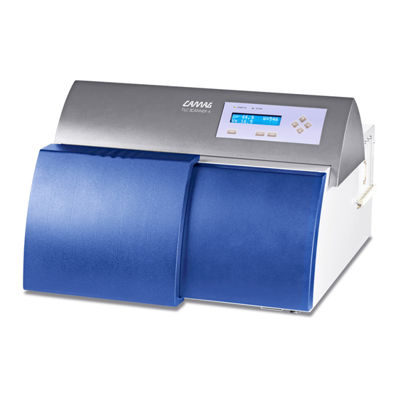
TLC Scanner 4 Introduction Intended use: The CAMAG TLC SCANNER 4 (Fig.1) is designed for densitometric measurement of thin-layer chromatograms and other objects up to 200x200 mm in size. While the Scanner 4 performs the actual densitometric measure- ment, data is processed by the CAMAG visionCATS/winCATS Pla- nar Chromatography Manager running on a connected computer. -
Page 4: Precautions
Conformity (DoC). The instrument complies with safety class 1 and has been designed for indoor use only (IP 20). Further, this device has passed the CAMAG Quality Assurance tests and has been delivered in safe operation condition. For detailed instrument data see chapter technical data •... - Page 5 • Only authorized personnel may open the instrument. Service and repair is only to be performed by trained specialists. Use spare parts and consumables supplied by CAMAG only. The warranty is voided if parts from other sources are used. Check...
-
Page 6: Parts Information
362.0008 2 Fuse 230V, 2A slow blow Power cord 705.0018 Screwdriver Allen key type 2.5mm 705.0012 Screwdriver Allen key type 3.0 mm B.027.6200E 1 Manual TLC Scanner 4 Spare parts Part No. Description 027.6440 Mercury vapor lamp 027.6441 Deuterium lamp 027.6442... -
Page 7: Unpacking And Installation
Check with chapter Parts information whether any parts are miss- ing. The TLC Scanner 4 is a high precision instrument. Place it on a suit- able, plain and horizontal working surface. Its measuring sensitivity is impaired by dust, corrosive vapours, shocks and vibrations. -
Page 8: Conditions For The Installation
TLC Scanner 4 • Avoid placing the instrument near equipment that radiates heat. Do not place the instrument near gas burners, electric heaters or ovens. • Do not place the instrument near equipment that generates in- tense magnetic fields such as electric welding equipment, high frequency furnaces, pole transformers, etc. -
Page 9: Connections
TLC Scanner 4 3.4 Connections 3.4.1 Power supply The left side of the Scanner 4 shows the power socket with the ON/OFF switch (2), the voltage selector-switch (1) and the connec- tion (tubing nipple) for the nitrogen gas supply (3). -
Page 10: Peripheral Equipment
TLC Scanner 4 3.4.2 Peripheral equipment The RS232 plug (1) for connecting the Scanner 4 to the computer (“Only for connection of IECxxxxx approved equipment”) is located on the right side of the Scanner 4 housing. Fig. 4: RS232 connection 3.4.4 Nitrogen flushing of the monochromator... -
Page 11: Optional Foil-Holder/Plate-Stopper
TLC Scanner 4 Fig. 5: Placement of TLC/HPTLC plate and magnetic strip 3.6 Optional Foil-Holder/Plate-Stopper • The standard plate stopper is in a fixed position and is for glass TLC/HPTLC plates. It can also be used for foils. Note: with foils there is a 2 mm offset in Y direction! •... -
Page 12: The Keypad And Display
TLC Scanner 4 Fig. 6: Exchanging Foil-holder/Plate-stopper The keypad and display Switch ON the Scanner 4 by pressing the power switch towards I. (Fig. 3 (2)) 4.1 ILLUM (Compartment illumination) Press the ILLUM key to ignite the compartment illumination. The Scanner 4 automatically moves the monochromator to 546nm and ignites the Tungsten lamp in order to make the slit visible. -
Page 13: Arrow Keys (Move Stage)
TLC Scanner 4 4.3 Arrow keys (Move stage) By pressing one of the arrow keys, the scanning table will move in the direction of the arrow. The table will start slowly and acceler- ates if the key remains pressed. The current position of the table in X and Y is displayed live. -
Page 14: Maintenance
TLC Scanner 4 Maintenance Dust and powder (e.g. from TLC plates) that has accumulated in the measuring compartment has to be removed with a vacuum cleaner regurarly. Maintenance should be performed only by authorized technicians who are familiar with the Scanner’s technical and functional char- acteristics. -
Page 15: Deuterium Lamp Exchange
The position of the lamp will be optimized in the ray path. The emitted light energy of the new lamp will be measured and saved for use in the respective procedure of CAMAG software. 5.3 Deuterium lamp exchange The Deuterium lamp (cat. no. 027.6441) - Fig.8 (3), has a life time of about 1000 hours. -
Page 16: Compartment Illumination Lamp Exchange
TLC Scanner 4 Fig. 8: The lamp compartment 5.5 Compartment illumination lamp exchange • Remove the knurled screw Fig.9 (1) of the PM-cover on the front side. Pull the PM-cover towards left Scanner 4 side and take it out of the Scanner (2). Inset the PM-cover carefully in the op- posite manner (3) Fig.9 and Fig.10. - Page 17 TLC Scanner 4 Fig. 10: Taking out the PM-cover. Fig.11: Replacing the compartment illumination lamp. Instruction Manual, June 2018 Page 16...
-
Page 18: Maintenance Data Sheet
TLC Scanner 4 5.6 Maintenance data sheet CAMAG Maintenance data sheet TLC Scanner 3/4 April 2012/UB Purpose The maintenance data sheet informs about maintenance interval of the respective instru- ment as well as the proposal for IQ/OQ interval if applicable. In addition, it identifies con- sumable parts with the respective replacement cycle. -
Page 19: The User-Dialog
• Press or to save the new value. The new Baud rate is now valid. (recommended 19`200 baud) The new Baud rate will be recognized automatically by the CAMAG software at the next connection. 6.2 LCD-Contrast The keypad display of the Scanner 4 can be adapted to the current light conditions by means of this function in the USER-Dialog. -
Page 20: New D2 Lamp
TLC Scanner 4 • Press the key LOAD POS to start the automatic optimization routine or any other key to get back to the USER DIALOG. • Press to quit the USER DIALOG or to select another func- tion. -
Page 21: Uv Intensity Of Compartment Illumination
49 30 516 55 50 · Fax 49 30 795 70 73 · E-Mail: infoberlin@camag.com CAMAG Scientific Inc. (USA) · 515 Cornelius Harnett Drive · Wilmington, NC 28401 Telephone 800 334 3909 · Fax 910 343 1834 · E-Mail: tlc@camag.com www.camag.com... - Page 23 Notes: __________________________________________________________________________________ __________________________________________________________________________________ __________________________________________________________________________________ __________________________________________________________________________________ __________________________________________________________________________________ __________________________________________________________________________________ __________________________________________________________________________________ __________________________________________________________________________________ __________________________________________________________________________________ __________________________________________________________________________________ __________________________________________________________________________________ __________________________________________________________________________________ __________________________________________________________________________________ __________________________________________________________________________________ __________________________________________________________________________________...
- Page 24 Notes: __________________________________________________________________________________ __________________________________________________________________________________ __________________________________________________________________________________ __________________________________________________________________________________ __________________________________________________________________________________ __________________________________________________________________________________ __________________________________________________________________________________ __________________________________________________________________________________ __________________________________________________________________________________ __________________________________________________________________________________ __________________________________________________________________________________ __________________________________________________________________________________ __________________________________________________________________________________ __________________________________________________________________________________ __________________________________________________________________________________...
- Page 25 Notes: __________________________________________________________________________________ __________________________________________________________________________________ __________________________________________________________________________________ __________________________________________________________________________________ __________________________________________________________________________________ __________________________________________________________________________________ __________________________________________________________________________________ __________________________________________________________________________________ __________________________________________________________________________________ __________________________________________________________________________________ __________________________________________________________________________________ __________________________________________________________________________________ __________________________________________________________________________________ __________________________________________________________________________________ __________________________________________________________________________________...
Need help?
Do you have a question about the TLC SCANNER 4 and is the answer not in the manual?
Questions and answers