Advertisement
Quick Links
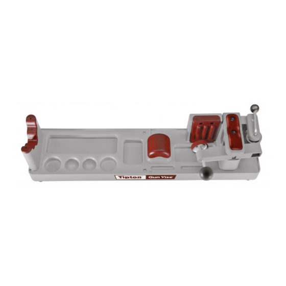
C: Pad Assembly
1. Install the Forend Pad by firmly
pressing the 5 plugs into the holes
in the Base as shown.
Usage Instructions:
1. Place the Gun Vise on a flat surface with enough clearance for the barrel to protrude out the left side.
2. Make sure the Cam Lever is turned toward the back of the Vise.
3. Place your gun into the Gun Vise as shown.
4. Turn the Cam Lever to the front of the Vise.
5. Turn the Adjustment Knob until the Clamp Pad just touches the stock.
6. Open the Cam Lever again, and turn the Adjustment Knob clockwise 2-3 more turns.
7. Turn the Clamp Lever to the front of the Vise. This should tightly clamp your gun while
allowing the Cam Lever to lock into the fully forward position.
NOTE: For best results, ensure the Clamp Pad is firmly in contact with the stock and
not positioned on the edge of the cheek piece.
2. Install the Grip Pad by pressing the
two plugs inside the Pad through the
holes in the base as shown. The pad
should "snap" into place.
3.
3. Install the Rear Pad by sliding it
downward from the top. The two
tabs on the top and the three tabs
at the bottom of the pad should align
with the slots in the base.
5.
4.
Assembly and Usage Instructions
Product #: 782731
Instructions #: 690000
2.
WARNING:
THIS PRODUCT IS NOT A BENCH
REST. DO NOT SHOOT A FIREARM WHILE IT IS
CLAMPED INTO THIS PRODUCT.
Revision C
Advertisement

Summary of Contents for Battenfeld Tipton Gun Vise
- Page 1 C: Pad Assembly 2. Install the Grip Pad by pressing the 3. Install the Rear Pad by sliding it 1. Install the Forend Pad by firmly pressing the 5 plugs into the holes two plugs inside the Pad through the downward from the top.
- Page 2 B: Cam Assembly Thank you for purchasing a Tipton Gun Vise. Assembly of this product is very easy and requires only a Phillips head 1. Hold the Cam in one hand and the Cam Lever Assembly screwdriver. Please take a moment to locate all of the parts shown in the photo below.