
Subscribe to Our Youtube Channel
Summary of Contents for TIM Mirus MC ISO
- Page 1 Additional Information MIRUS Controller Software version 2.03.02 Hardware version 2.n...
- Page 2 GS-1 manufacturer number: 426066592 b. Number of articles: 001 c. Check digit: 3 MIRUS™ and are trademarks of Technologie Institut Medizin GmbH (TIM). Other brand names or product names used in this manual are trademarks or registered trademarks of their respective holders.
-
Page 3: Table Of Contents
Table of contents 1 Introduction 1.1 MIRUS System ......................1-2 1.1.1 Definitions ......................1-2 1.1.2 General information ....................1-2 1.1.3 MIRUS Controller ....................1-3 1.1.4 MIRUS Exchanger ....................1-4 1.1.5 Device user interface ..................... 1-4 1.2 Symbols on the device ....................1-5 1.3 Symbols used in this manual .................. - Page 4 0 Table of contents 2.1.17 Maintenance ......................2-9 2.1.18 Repairs ........................ 2-9 2.2 Fail safe mode ......................2-10 2.3 Notification of serious incidents .................. 2-10 2.4 Safety features ......................2-11 2.5 Warnings in these Instructions for use ................ 2-12 3 General description 3.1 Intended use.........................
- Page 5 0 Table of contents 5.1.4 Stopping application of anaesthetic (VA) ..............5-5 5.1.5 Filling during operation ................... 5-6 5.1.6 Turning off MIRUS Controller ................. 5-8 5.2 Additional settings ......................5-9 5.2.1 Alarm settings ......................5-9 5.2.2 Setting on-screen language ................. 5-10 5.2.3 Setting CO unit ....................
- Page 6 0 Table of contents 7.2.5 3 High priority alarm handling ................7-9 7.2.6 Low priority alarm handling .................. 7-10 7.3 Alarm messages ......................7-11 7.3.1 Patient alarms ...................... 7-11 7.3.2 Technical alarms ....................7-12 7.4 Other messages ......................7-14 7.4.1 Messages during Power up test ................7-14 7.4.2 Messages during System test ................
-
Page 7: Introduction
Introduction MIRUS System ......................2 1.1.1 Definitions ......................2 1.1.2 General information ..................... 2 1.1.3 MIRUS Controller ....................3 1.1.4 MIRUS Exchanger ....................4 1.1.5 Device user interface ................... 4 Symbols on the device ....................5 Symbols used in this manual ..................5 Graphical user interface .................... -
Page 8: Mirus System
1.1.1 Definitions "MIRUS System" in this instruction for use means "system" in terms of article 12 MDD and describes a functioning composition of three separate registered medical products: MIRUS Controller, legal manufacturer "Technologie Institut Medizin GmbH (TIM)" • • MIRUS Reflector, legal manufacturer "PALL Medical, a division of PALL International Sàrl". -
Page 9: Mirus Controller
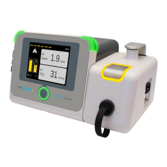
1 Introduction 1.1.3 MIRUS Controller Alarm lights Fill port Park Bay Power connection Terminal for connecting an equipotential bonding conductor Interface receptacle Confirm button Slot for SD cards (downloading of event log data or for SW updates) Touch screen Fire wire port. Serial data output for PDMS etc. Nurse call port to forward high priority alarms LAN port, used for production and service purposes and is switched off during application for safety reasons... -
Page 10: Mirus Exchanger
1 Introduction 1.1.4 MIRUS Exchanger MIRUS Reflector Interface connector MIRUS Filter (Multi patient device. (Single patient device. Use up to 7 days) Use up to 48 h) 1.1.5 Device user interface Touch screen Operate MIRUS Controller by pressing buttons on the graphical user interface via touch sensitive screen. -
Page 11: Symbols On The Device
1 Introduction 1.2 Symbols on the device STK label (in Germany): Indicates when the next safety check in accordance with §6 Medical Device Operator Ordinance (MPBetreibV) is required. Warranty seal: Warranty void if seal is broken 1.3 Symbols used in this manual Operate by touching an icon or symbol. -
Page 12: Graphical User Interface
1 Introduction 1.4 Graphical user interface 1.4.1 Symbols on menu buttons Home (Standard operation screen) Patient data settings MAC Pilot settings. Set wash-in speed Respiratory monitoring Alarm settings MULTI settings: see the following 4 tags Filling MIRUS settings Time settings Service Turn off MIRUS Controller, SW 2.03.02, Additional Information (Master - en-GB) -
Page 13: Status Icons
1 Introduction 1.4.2 Status icons “Life line”. Animated when delivery is in progress, stationary when delivery is paused. Not visible when delivery is stopped. Lung Symbol “breathes”; is animated in operation mode. Reflector symbol; shows remaining allowed operation time of MR in anaesthetic colour. -
Page 14: Buttons
1 Introduction High priority alarm sound active. High priority alarm sound muted. Low priority alarm sound active. Low priority alarm sound permanently muted. 1.4.3 Buttons In order of appearance Repeat (e.g. a failed self-test in starting procedure). Turn off device. Start delivery of anaesthetic. - Page 15 1 Introduction MAC button showing unit and current value. Press to be able to set new value. Apnoea time Setting button showing unit and current value. Press to set value with arrow buttons aside, e.g. Alarm volume. Instructive animation to open Fill port. Activate mode.
-
Page 16: Button States And Behaviour
1 Introduction 1.4.4 Button states and behaviour Buttons to select and confirm Normal state; not pressed. Button is pressed; confirmation with Confirm button is needed. Button is confirmed and now highlighted in anaesthetic colour. Buttons to set a value Inactive button. Normal state;... -
Page 17: Colour Code Used In Graphical User Interface
1 Introduction 1.4.5 Colour code used in graphical user interface Colour in graphical user interface for Sevoflurane. For demonstration purposes, Sevoflurane / yellow highlighting colour is used in this IFU. Colour in graphical user interface for Isoflurane. Colour in graphical user interface for Desflurane. MIRUS Controller, SW 2.03.02, Additional Information (Master - en-GB) 1-11... -
Page 18: Mirus Controller Screens
1 Introduction 1.5 MIRUS Controller screens 1.5.1 MIRUS Start up screens Initial screen Power up test System is starting and performing safety tests HW 2.n SW 2.03.02 with its components. One moment please… System test System is performing safety tests with its HW 2.n SW 2.03.02 components. -
Page 19: Mirus Operating And Configuration Screens
1 Introduction Safety note HW 2.n SW 2.03.02 Safety note needs to be confirmed by user. It is also possible to turn off device. 1.5.2 MIRUS Operating and Configuration screens On-Call screen HW 2.n SW 2.03.02 System is up and waiting for user action. Power up test and System test successfully completed on 11.01.2013 at 10:25:00. - Page 20 1 Introduction Home screen delivery active etSevo: 1.9 : 31 etCO Vol% mmHg Set MAC value and pause or stop the delivery. Snooze Screen Appears only during active delivery and no activity on the touch screen for 10 minutes. Patient data screen Adjust: gender •...
- Page 21 1 Introduction MAC Pilot screen no delivery This screen is to set the wash-in parameter. Choose wash-in speed by selecting turtle = slow • rabbit = medium or • cheetah = fast • Wash-in speed Comment: Wash-in speed default is “rabbit”. MAC Pilot screen delivery active This screen is to set the wash-in parameter.
- Page 22 1 Introduction Alarm setting screen Adjust: etCO etCO • etCO minimum • etCO maximum • etVA minimum etSevo etSevo • etVA maximum Apnoea time • Alarm volume (maximum) • Apnoea time Alarm vol. Configuration/Setting screens This screen is comprised of sub screens which are described below.
- Page 23 1 Introduction Settings screen Adjust: • language • unit Language Refer to Chapter 8.5 for available settings. English mmHg Time setting screen First set your time zone (UTC ± xh) and then date and local time. Comment: Automatic change from daylight savings to standard time.
-
Page 24: Mirus Software Update Screen
1 Introduction Turn Off screen Turn off MIRUS Controller using this screen. Comment: Delivery must be stopped to be able to turn off. No patient should be attached to the MIRUS System. 1.5.3 MIRUS Software update screen Software update HW 2.n SW 2.03.02 Only appears when SW update SD card was recognised. -
Page 25: Mirus Controller Modes
1 Introduction 1.6 MIRUS Controller modes OFF state Device is turned off and not connected to mains supply. OFF mode (Standby) Device is connected to mains supply but not turned on yet. Fail safe Device has detected a major failure and has moved into a safe mode. -
Page 26: Abbreviations And Terms Used In This Manual Or On The Equipment
1 Introduction 1.7 Abbreviations and terms used in this manual or on the equipment In alphabetical order: Alternating current. Direct current. Anaesthesia Workstation. breaths per minute. BTPS Body temperature and pressure, saturated. Desflurane. DOGA Diffusion Optimized Gas Application. Consumption optimising application of VA. - Page 27 1 Introduction Minute Volume, the breathing volume of a patient per minute. Minute volume, expiratory; Unit: L/min. Minute volume, inspiratory. Non Invasive Ventilation. Ventilation with a mask or a helmet Operating Room, also Operating Theatre. Highest airway pressure, measured with last breath. peak PACU Post Anaesthetic Care Unit.
- Page 28 1 Introduction Notes 1-22 MIRUS Controller, SW 2.03.02, Additional Information (Master - en-GB)
-
Page 29: Safety
Safety General safety information ..................2 2.1.1 Safe operation ....................... 2 2.1.2 Symbols and product labels ................... 2 2.1.3 Electrical supply ....................2 2.1.4 Built-in emergency power supply (UPS battery) ............. 3 2.1.5 Positioning ......................3 2.1.6 Use of volatile anaesthetics ................... 3 2.1.7 Devices required for use of the MIRUS System ............. -
Page 30: General Safety Information
2 Safety 2.1 General safety information 2.1.1 Safe operation If the MIRUS Controller is not used as described in the Instructions for use, this may endanger the patient and other persons or cause equipment damage. user should familiarise themselves with these Instructions for use before putting the MIRUS Controller into service, and must follow them during use. -
Page 31: Built-In Emergency Power Supply (Ups Battery)
2 Safety 2.1.4 Built-in emergency power supply (UPS battery) The MIRUS Controller is equipped with an internal emergency power supply (UPS battery). If the mains power supply fails, the emergency power supply is automatically activated and bridges the time until the mains power supply is restored (see information in Chapter 8.2). Inhalation sedation can be continued with limited functionality. -
Page 32: Devices Required For Use Of The Mirus System
MIRUS System for use together with the MIRUS System. Only use with devices specified by the manufacturer. Comment: The current list of compatible devices can be found on the website of the manufacturer Technologie Institut Medizin GmbH (TIM): https://tim-gmbh.de/en/mirus-docs/ MIRUS Controller, SW 2.03.02, Additional Information Master (en-GB) - Page 33 2 Safety Anaesthesia devices If the MIRUS Controller is used together with an anaesthesia device for low-flow anaesthesia, this may result in the generation of heat and humidity in the rebreathing system due to the CO absorption process. If there is an increase in the airway resistance, this may pose a risk to the patient.
-
Page 34: Before Every Use
2 Safety Pressurised inhalation If the MIRUS Controller is used in combination with pressurised inhalation (metered-dose inhaler), the device’s internal gas monitor may misinterpret the inhaler’s propellant gas as a volatile anaesthetic, and thus reduce the dosage of volatile anaesthetic. This can result in short-term underdosing and thus pose a risk to the patient. -
Page 35: Alarms
2 Safety The use of volatile anaesthetics can affect the haemodynamic status of a patient and put him/her at risk. Ensure cardiovascular monitoring of the patient. An elevated airway resistance may endanger the patient. Monitor the patient's airway resistance. Monitor the MIRUS Filter for occlusion or accumulation of patient secretions, and replace when necessary. -
Page 36: Modifications
2 Safety 2.1.13 Modifications Modifications to the MIRUS Controller may cause malfunctions, which may endanger the patient and other persons or cause equipment damage. Modifications to the MIRUS Controller may only be performed by the manufacturer or by technical personnel expressly authorised by the manufacturer. 2.1.14 Accessories The MIRUS Controller has been tested using accessories from the accessory list. -
Page 37: Infection Risk
2 Safety Electromagnetic interference If devices that emit electromagnetic radiation (e.g. mobile telephones or medical electrical devices such as defibrillators or electrosurgical devices) are used too close to the MIRUS Controller, the proper functioning of the MIRUS Controller may be impaired by electromagnetic interference. -
Page 38: Fail Safe Mode
2 Safety 2.2 Fail-safe mode Safe mode means: screen is blank • no volatile anaesthetic agent is • delivered alarm lights are flashing in red • confirm button is flashing in red • audible alarm sound • To silence the audible alarm, press the Confirm button for at least 4 seconds. MIRUS Controller now turns off flashing red LEDs and stops alarm sound. -
Page 39: Safety Features
2 Safety 2.4 Safety features The MIRUS Controller is equipped with monitor functions for monitoring the device status and thus detecting changes in parameters. Changes in parameters may be caused by: Changes in patient status • Changes in the settings •... -
Page 40: Warnings In These Instructions For Use
2 Safety 2.5 Warnings in these Instructions for use Warnings highlight safety-relevant information. In the Instructions for use, warning words and symbols are used to flag actions that could endanger people or cause equipment damage. Warnings contains information about a possible hazard and instructions on how to avoid the hazard. -
Page 41: General Description
General description Intended use ....................... 2 Operater and user qualification ................... 2 3.2.1 Qualified medical personnel ..................2 3.2.2 Preparation personnel ..................... 2 3.2.3 Maintenance personnel ................... 2 Contraindications ......................3 Facility requirements ....................3 Gas supply ........................4 Agent supply ....................... 4 Functional description .................... -
Page 42: Intended Use
3 General description 3.1 Intended use The MIRUS Controller is part of the MIRUS System. It is intended for use in the administration of volatile anaesthetics to patients with an inspiratory tidal volume ≥ 200 mL. The MIRUS Controller can only be operated in combination with the MIRUS Reflector. For hygienic and safety reasons, the MIRUS System can only be connected to the patient via the MIRUS Filter. -
Page 43: Contraindications
3 General description 3.3 Contraindications Do not use the MIRUS System on patients whose ventilation requires an inspiratory tidal volume of less than • 200 mL, on patients for whom the use of volatile anaesthetics is contraindicated, • • on entirely spontaneously breathing patients without a ventilator equipped with a safety respiration mode (apnoea back-up), with jet or high-frequency ventilators, •... -
Page 44: Gas Supply
3 General description WARNING Potential patient hazard due to device malfunction resulting from incorrect ambient conditions Only operate and store the MIRUS Controller in accordance with the temperature, pressure humidity specifications (see Chapter 8.1). If the temperature of the MIRUS Controller is higher or lower than the room temperature (according to the specifications), wait approx. -
Page 45: Functional Description
3 General description 3.7 Functional description The MIRUS Controller is an electronic vaporiser that allows the user to administer a defined concentration of volatile anaesthetic to a patient. The MIRUS Controller uses a respiratory measurement system, which is integrated in the patient’s ventilation system via the MIRUS Reflector, to measure the patient’s breathing activity and volumes. -
Page 46: System Controls
3 General description 3.8 System controls The MIRUS Controller is operated by a touch screen and a Confirm button. The principle of operation is: • select a parameter/function on touch screen. adjust desired value (e.g. by up/down arrows). • confirm chosen value. •... -
Page 47: Handling Before First Use Of Mirus Controller
3 General description 3.9 Handling before first use of MIRUS Controller 3.9.1 Cleaning before first use The MIRUS Controller does not come sterilised; the device has to be cleaned completely by the user before it is used clinically for the first time. 3.9.2 Initial filling before first use The MIRUS Controller always comes with an empty reservoir. - Page 48 3 General description Notes MIRUS Controller, SW 2.03.02, Additional Information Master (en-GB)
-
Page 49: Preparation
Preparation 4.1 Mains supply ........................2 4.2 System warming up phase ....................3 4.3 Connection to the MIRUS Reflector ................. 3 4.4 Starting MIRUS Controller ....................5 4.5 Filling of the reservoir during start up ................8 4.6 Self test ..........................11 4.7 Anomaly in start up sequence ..................12 MIRUS Controller, SW 2.03.02, Additional Information Master (en-GB) -
Page 50: Mains Supply
4 Preparation 4.1 Connection to mains supply Verify your local AC line supply voltage matches the rated device’s voltage on the serial plate. Comment: Use only the original power cable! Plug the power cable into the line inlet on the right side of the device. -
Page 51: Mains Supply
4 Preparation 4.2 System warming up phase For functional reasons, MIRUS Controller must perform a system warming up phase. This phase is initialised the moment MIRUS Controller is connected to the mains supply (AC). Length of this phase is dependent on used anaesthetic and filling level inside MIRUS. MIRUS Controller VA Length of warming up Isoflurane... - Page 52 4 Preparation 2. Lift Park Bay clip and place MIRUS Reflector with large opening facing down under the clip fitting the nozzle. Release clip gently. 3. Now remove black connector protection and insert MIRUS Interface plug into the MIRUS Connector receptacle until mechanically locked.
-
Page 53: Starting Mirus Controller
4 Preparation 4.4 Starting MIRUS Controller Comment: To avoid interruption in start-up, ensure connected AC (refer to Chapter 4.1 for more information). • filled internal reservoir (refer to Chapter 4.5 for more information). • • MIRUS Reflector is placed in Park Bay (refer to Chapter 4.3 for more information). 1. - Page 54 4 Preparation 4. MIRUS Power up test is in progress. HW 2.n SW 2.03.02 One moment please… 5. The MIRUS Controller completes Power up test successfully. In any other case, HW 2.n SW 2.03.02 the MIRUS Controller will let you know by messages and give instructions.
- Page 55 4 Preparation 7. In case the warming up phase is not finished yet a corresponding message HW 2.n SW 2.03.02 appears on screen. System warming up. Please wait… Refer to Chapter 4.2 for more information about length of warming up. 8.
-
Page 56: Filling Of The Reservoir During Start Up
Wait for a filling prompt (message on the screen) and follow the instructions. Comment: You can find a list of the available bottle adapters in Chapter 9 or at https://tim-gmbh.de/en/bottle-adapter/ Comment: You can find further information on the bottle adapter in the manufacturer’s Instructions for use. - Page 57 4 Preparation 2. During start up sequence: MIRUS Controller wants you to refill reservoir. HW 2.n SW 2.03.02 Press animated icon with the Fill port flap. The agent reservoir is empty. To continue please refill the device. IMPORTANT Risk of equipment damage To open Fill port please confirm.
- Page 58 4 Preparation 7. Take the bottle with the adapter and insert it vertically, with the adapter facing the Fill port. Press the bottle into the Fill port gently until you feel a mechanical stop that opens the spring loaded valves. 8.
-
Page 59: Self Test
4 Preparation 4.6 Self-test The MIRUS Controller software contains self-test capabilities that verify whether the software, the pneumatic and electrical components, the MIRUS Reflector and the gas monitor work properly. These self-tests are (in sequential order) • Power up test System test •... -
Page 60: Anomaly In Start Up Sequence
4 Preparation If the MIRUS Reflector is not parked in the Park Bay the following message appears on HW 2.n SW 2.03.02 the screen. System test failed! Reflector not in Park Bay. Please insert the Reflector and repeat the System test. During System test the MIRUS Controller starts the operation of the heating system and checks the following:... -
Page 61: Operation
Operation 5.1 Working with MIRUS Controller ..................2 5.1.1 Setting MAC (Vol%) ....................2 5.1.2 Starting application of anaesthetic (VA) ..............3 5.1.3 Pausing application of anaesthetic (VA) ..............4 5.1.4 Stopping application of anaesthetic (VA)..............5 5.1.5 Filling during operation ....................6 5.1.6 Turning off MIRUS Controller .................. -
Page 62: Working With Mirus Controller
5 Operation 5.1 Working with MIRUS Controller 5.1.1 Setting MAC (Vol%) HW 2.n SW 2.03.02 : 31 etSevo: 0.0 etCO mmHg Vol% Power up test and System test successfully completed on 11.01.2013 at 10:25:00. To continue please choose a menu button on the right. etSevo: 0.0 etCO : 31... -
Page 63: Starting Application Of Anaesthetic (Va)
5 Operation 5.1.2 Starting application of anaesthetic (VA) HW 2.n SW 2.03.02 etSevo: 0.0 etCO : 31 Vol% mmHg Power up test and System test successfully completed on 11.01.2013 at 10:25:00. To continue please choose a menu button on the right. etSevo: 0.0 etCO : 31... -
Page 64: Pausing Application Of Anaesthetic (Va)
5 Operation 5.1.3 Pausing application of anaesthetic (VA) etSevo: 1.9 etCO : 31 etSevo: 1.9 etCO : 31 mmHg Vol% Vol% mmHg etSevo: 1.9 etCO : 31 etSevo: 1.9 etCO : 31 Vol% mmHg mmHg Vol% etSevo: 1.9 etCO : 31 Vol% mmHg Comment:... -
Page 65: Stopping Application Of Anaesthetic (Va)
5 Operation 5.1.4 Stopping application of anaesthetic (VA) etSevo: 1.9 etCO : 31 etSevo: 1.9 etCO : 31 mmHg mmHg Vol% Vol% etSevo: 1.9 etCO : 31 Vol% mmHg etSevo: 1.9 : 31 etSevo: 0.0 etCO : 31 etCO Vol% mmHg Vol% mmHg... -
Page 66: Filling During Operation
5 Operation 5.1.5 Filling during operation CAUTION Hazard to persons if volatile anaesthetic accumulates in the environment around the patient. Observe the Instructions for use of the bottle adapter. Avoid spilling liquid volatile anaesthetic. The fill valve below the fill port flap must never be pressed down manually. - Page 67 5 Operation Reservoir empty Reservoir empty [24] [24] since 15 sec since 20 sec 1:45 min 1:40 min Mute Mute : 31 : 31 etSevo: 1.9 etCO etSevo: 1.9 etCO mmHg mmHg Vol% Vol% Reservoir empty Reservoir empty [24] [24] since 25 sec since 30 sec 1:35 min...
- Page 68 5 Operation Reservoir empty [24] since 40 sec 1:20 min Mute Filling level Filling level max 190 ml max190 ml The maximum level is Thank you! reached. Please start the Please close the filling process. Fill port. IMPORTANT Comment: Risk of equipment damage VA delivery is maintained during filling To avoid the ingress of particles and other reservoir as long as internal pressure is...
-
Page 69: Turning Off Mirus Controller
5 Operation 5.1.6 Turning off MIRUS Controller Comment: Only if VA is not delivered “Turn OFF” tag becomes active. Refer to Chapter 5.1.4. etSevo: 0.0 etCO : 31 Vol% mmHg Please confirm to turn off the MIRUS Controller. Please place the MIRUS Reflector on the Reflector Park Bay. -
Page 70: Additional Settings
5 Operation 5.2 Additional settings 5.2.1 Alarm settings The alarm settings are set by the manufacturer to default values (see Chapter 8.8.1). If the settings are changed, they will be automatically reset to default values during a system test. etCO etCO etCO etCO... -
Page 71: Setting On-Screen Language
5 Operation 5.2.2 Setting on-screen language Language Language English English mmHg mmHg Language Language English German mmHg mmHg Sprache Deutsch mmHg Refer to Chapter 8.1 for available languages. MIRUS Controller, SW 2.03.02, Additional Information Master (en-GB) 5-11... -
Page 72: Setting Co Unit
5 Operation 5.2.3 Setting CO unit Language Language English English mmHg mmHg Language Language English English mmHg Language English Refer to Chapter 8.5 for available units. 5-12 MIRUS Controller, SW 2.03.02, Additional Information Master (en-GB) -
Page 73: Setting Time Zone, Date Or Time
5 Operation 5.2.4 Setting Time zone, date or time MIRUS Controller, SW 2.03.02, Additional Information Master (en-GB) 5-13... -
Page 74: Setting Patient Data - Gender
5 Operation 5.2.5 Setting Patient data – Gender years years Size Size Weight Weight kg (IBW) kg (IBW) years Size Weight kg (IBW) years Size Weight kg (IBW) 5-14 MIRUS Controller, SW 2.03.02, Additional Information Master (en-GB) -
Page 75: Setting Patient Data - Age
5 Operation 5.2.6 Setting Patient data – Age Years years Size Size Weight Weight kg (IBW) kg (IBW) years years Size Size Weight Weight kg (IBW) kg (IBW) years Size Weight kg (IBW) Refer to Chapter 8.5 for available values. MIRUS Controller, SW 2.03.02, Additional Information Master (en-GB) 5-15... - Page 76 5 Operation 7. Before: 8. After: etSevo: 1.9 etCO : 31 etSevo: 1.9 etCO : 31 Vol% Vol% mmHg mmHg 5-16 MIRUS Controller, SW 2.03.02, Additional Information Master (en-GB)
-
Page 77: Setting Mac Pilot Wash-In Speed
5 Operation 5.2.7 Setting MAC Pilot Wash-in speed Wash-in speed Wash-in speed Wash-in speed Wash-in speed MIRUS Controller, SW 2.03.02, Additional Information Master (en-GB) 5-17... - Page 78 5 Operation Notes 5-18 MIRUS Controller, SW 2.03.02, Additional Information Master (en-GB)
-
Page 79: Cleaning And Maintenance
Cleaning and maintenance Cleaning ........................2 General information ....................2 Cleaning the individual components ................ 3 Maintenance ....................... 4 General information ....................4 Schedule ......................... 4 Visual inspection ..................... 5 Electrical safety test ....................5 Checking gas monitor ....................6 Checking pump ....................... -
Page 80: Cleaning
6 Cleaning and maintenance 6.1 Cleaning General information The MIRUS Controller is a hygienically non-critical medical device. The device surface and the cables are accessible to the user. The surface disinfectants listed in the following table are suitable for wipe disinfection of the device surfaces. -
Page 81: Cleaning The Individual Components
6 Cleaning and maintenance Cleaning the individual components MIRUS Controller surface Turn off the MIRUS Controller and ensure that the mains power cord is disconnected. Make sure the Fill port is closed. Remove MIRUS Reflector and interface plug. Make sure the receptacle token is placed in the MIRUS Reflector receptacle and the receptacle is sealed. -
Page 82: Maintenance
6 Cleaning and maintenance 6.2 Maintenance General information WARNING Risk to persons from volatile anaesthetic in the MIRUS Controller Volatile anaesthetic may leak out and contaminate the environment. Empty out the MIRUS Controller before maintenance, as described in Chapter 6.3. WARNING Infection risk The MIRUS Controller may be contaminated by pathogens. -
Page 83: Visual Inspection
User / Operator soon as software update is available. Comment: For maintenance report template and for further information to the tests please contact the manufacturer TIM GmbH via: service@tim-products.de Visual inspection Inspect the MIRUS Controller for distortion, deterioration and cracks: ... -
Page 84: Checking Gas Monitor
6 Cleaning and maintenance Checking gas monitor In this test the gas monitor is tested for its measurement accuracy. The following accessories are required (refer to Chapter 6.6): Calibration gas kit Isoflurane containing = 4.5 – 5.0 Vol% = 1.0 – 2.0 Vol% = 30 –... -
Page 85: Checking Pump
6 Cleaning and maintenance Checking pump In this test the pump is tested for its performance. The following accessories are required (refer to Chapter 6.6): Air/Gas flow calibrator from a manufacturer of your choice. Range: 10 to 1000 mL/min Accuracy: ±... -
Page 86: Safety Function Test
6 Cleaning and maintenance Safety function test In this test all safety relevant functions of the MIRUS Controller are tested by the device itself. The following accessory is required (refer to Chapter 6.6): MIRUS Reference MR Perform the safety function test as follows: Mount the MIRUS Reference MR and perform a Power up Test and a System test according to Chapter 4. -
Page 87: Exchange Ups Battery
6 Cleaning and maintenance Exchange UPS battery The UPS battery must be changed every 24 months. The following accessory is required (refer to Chapter 6.6): UPS battery Torque wrench, adjustable to 0.6 Nm Carry out the exchange Turn the MIRUS Controller OFF and disconnect it from AC. Open the battery housing. -
Page 88: Exchange Fa Filter
6 Cleaning and maintenance Exchange fan filter The fan filter must be changed at least every 12 months or earlier if necessary. The following accessory is required (refer to Chapter 6.6): Replacement filter Carry out the exchange: Turn the MIRUS Controller OFF and disconnect it from AC. Open the filter housing. -
Page 89: Perform Software Update
Additional information on the SD card, the export process and forwarding of the event log data to the manufacturer (TIM) can be found in the Instructions for use of the SD card, which can be ordered in a print version or found online in the manufacturer’s website: https://tim-gmbh.de/en/mirus-docs/... -
Page 90: Draining The Reservoir
6 Cleaning and maintenance 6.3 Draining the reservoir To drain the reservoir, a MIRUS Draining Kit from manufacturer TIM is required (ordering information can be found in Chapter 9). Drain the reservoir as described in the supplied manufacturer’s Instructions for use. -
Page 91: Equipment For Safety Checks And Maintenance
6 Cleaning and maintenance 6.6 Equipment for safety checks and maintenance Safety checks Description Order code MIRUS Service Test plug MC-SC-TP-01 MIRUS Reference MR kit MC-SC-RMRKit MIRUS Event Log µSD card (Service purpose) MC-01-016 Calibration gas kit Isoflurane from a manufacturer of your choice containing = 4.5 –... - Page 92 6 Cleaning and maintenance Notes 6-14 MIRUS Controller, SW 2.03.02, Additional Information Master (en-GB)
-
Page 93: Alarms And Messages
Alarms and messages 7 Alarms and messages ......................1 7.1 Alarm modality ......................2 7.2 Alarm handling ......................3 7.2.1 Mute audible alarms ....................3 7.2.2 Audible alarm escalation ..................5 7.2.3 1 High priority alarm handling ................7 7.2.4 2 High priority alarm handling................ -
Page 94: Alarm Modality
7 Alarms and messages 7.1 Alarm modality The MIRUS Controller distinguishes between high and low priority alarms. The following describes the MIRUS Controller’s high and low priority alarms. Alarms only occur during operation and are shown in the following way: •... -
Page 95: Alarm Handling
7 Alarms and messages 7.2 Alarm handling 7.2.1 Mute audible alarms Low etCO [11] since 2 sec etSevo: 1.9 etCO : 25 Vol% mmHg Low etCO [11] since 2 sec etSevo: 1.9 etCO : 25 Vol% mmHg MIRUS Controller, SW 2.03.02, Additional Information Master (en-GB) - Page 96 7 Alarms and messages Low etCO [11] since 5 sec 1:58 min Mute etSevo: 1.9 etCO : 25 Vol% mmHg MIRUS Controller, SW 2.03.02, Additional Information Master (en-GB)
-
Page 97: Audible Alarm Escalation
7 Alarms and messages 7.2.2 Audible alarm escalation Comment: The alarm volume will escalate from 50% sound intensity up to the set volume (max. 100%) until alarm is muted. Comment: The set value for alarm volume represents the maximum sound level. First time of alarm appears Low etCO [11]... - Page 98 7 Alarms and messages Third time of alarm appears Low etCO [11] since 38 sec etSevo: 1.9 : 25 etCO Vol% mmHg Fourth time of alarm appears Low etCO [11] since 56 sec etSevo: 1.9 etCO : 25 Vol% mmHg ...
-
Page 99: St High Priority Alarm Handling
7 Alarms and messages 7.2.3 1 High priority alarm handling Low etCO [11] since 2 sec etSevo: 1.9 : 31 etCO etSevo: 1.9 etCO : 25 Vol% mmHg Vol% mmHg Low etCO Low etCO [11] [11] since 36 sec 1:58 min since 18 sec Mute etSevo: 1.9... -
Page 100: Nd High Priority Alarm Handling
7 Alarms and messages 7.2.4 2 High priority alarm handling Low etCO High etSevo [11] [10] since 38 sec 1:23 min since 28 sec mute etSevo: 1.9 etCO : 25 etSevo: 4.8 etCO : 25 Vol% mmHg Vol% mmHg High etSevo High etSevo [10] [10]... -
Page 101: Rd High Priority Alarm Handling
7 Alarms and messages 7.2.5 3 High priority alarm handling High etSevo Low Vti [10] [04] since 56 sec 1:58 min since 5 sec Mute etSevo: 4.8 etCO : 25 etSevo: 4.8 etCO : 25 Vol% mmHg Vol% mmHg Low Vti Low Vti [04] [04]... -
Page 102: Low Priority Alarm Handling
7 Alarms and messages 7.2.6 Low priority alarm handling Mains supply lost [33] et Sevo: 1.9 : 31 et CO Vol% mmHg Mains supply lost Mains supply lost [33] [33] : 31 etSevo: 1.9 etCO etSevo: 1.9 : 31 etCO Vol% mmHg Vol%... -
Page 103: Alarm Messages
7 Alarms and messages 7.3 Alarm messages The MIRUS Controller distinguishes between patient related alarms and technical alarms. 7.3.1 Patient alarms larm Prio. Device Cause Remedy action Apnoea [01] Pauses VA Patient stopped Check patient condition. delivery. breathing. Check interface for kinking. Obstruction Check ventilator settings. -
Page 104: Technical Alarms
7 Alarms and messages larm Prio. Device Cause Remedy action Low etVA [09] High The etVA Check patient condition. concentration has fallen below the Check alarm settings. lower alarm limit, while the VA Check, if VA application is application is active active. - Page 105 7 Alarms and messages Alarm Prio. Device Cause Remedy action Occlusion of [14] High Pauses VA A gas sampling or Check interface for kinking. Interface [15] delivery. measurement line is blocked. Check interface for condensation. Check MIRUS Filter. Make sure that the fresh gas flow of the anaesthesia device is at least 1.5 * MV.
-
Page 106: Other Messages
7 Alarms and messages 7.4 Other messages The MIRUS Controller software includes self-tests that determine if the operating software is functioning properly and if the electronic and pneumatic circuits are functional. The self-tests include: • Power up test (PUT) System test (ST) •... - Page 107 7 Alarms and messages Message Set condition Required user Device action (in order of action testing) Thank you! Power Fill port flap is None or turn off Performs Power up test will now closed. MIRUS Controller up test or turn proceed via turn off button.
- Page 108 7 Alarms and messages Message Set condition Required user Device action (in order of action testing) Sorry. A problem A technical failure Confirm to turn off Performs turn OFF has been was recognized MIRUS Controller. sequence as soon detected. The during Power up Then disconnect as user confirms...
-
Page 109: Messages During System Test
7 Alarms and messages 7.4.2 Messages during System test Messages generated during the System test are shown on the screen as follows: HW 2.n SW 2.03.02 System test active. Please wait… Message Set condition Required user Device action action (in order of testing) System test MIRUS Interface... - Page 110 7 Alarms and messages Message Set condition Required user Device action (in order of action testing) System test failed! MIRUS Interface Insert MIRUS Stops System test Reflector not in detected. Reflector into sequence until Park Bay. Please MIRUS Reflector Park Bay user activity or insert the not detected in...
- Page 111 7 Alarms and messages Message Set condition Required user Device action (in order of action testing) Sorry. A problem A technical failure Confirm to turn off Performs turn OFF has been was recognized MIRUS Controller. sequence as soon detected. The during System Then disconnect as user confirms...
-
Page 112: Safety Note In Screen
7 Alarms and messages 7.4.3 Safety note in screen Following safety note is generated in screen: HW 2.n SW 2.03.02 Message Set condition Required user Device action action WARNING Is shown after Confirm safety Moves to On-call Power up test and note or turn off mode after Never use an... -
Page 113: Messages During On-Call Mode
7 Alarms and messages 7.4.4 Messages during On-Call mode Messages generated during the On-Call mode are shown on the screen as follows: HW 2.n SW 2.03.02 Power up test and System test successfully completed on 11.01.2013 at 10:25:00. To continue please choose a menu button on the right. -
Page 114: Messages During Operation Mode
7 Alarms and messages 7.4.5 Messages during Operation mode During Operation mode some user activity is required. The messages generated are shown on the screens as follows: Filling level: max 190 ml To open Fill port please confirm. Message Set condition Required user Device action action... - Page 115 7 Alarms and messages Please confirm to turn off the MIRUS Controller. Message Set condition Required user Device action action Please confirm to User selected Confirm. Waits for user to turn off the MIRUS Turn OFF button confirm or resets Controller.
-
Page 116: Messages During Sw Update
7 Alarms and messages 7.4.6 Messages during SW update Messages generated during the SW update are shown on the screen as follows: HW 2.n SW 2.03.02 MIRUS Controller software update Software update card detected. Please press Play to start. Message Set condition Required user Device action... - Page 117 7 Alarms and messages Message Set condition Required user Device action action SD card defective. SD card integrity Remove SD card Denies SW SW update test failed. and press OK. update. cancelled. Please Will proceed with remove SD card regular start up and press OK.
- Page 118 7 Alarms and messages Notes 7-26 MIRUS Controller, SW 2.03.02, Additional Information Master (en-GB)
-
Page 119: Specifications
Specifications General ........................2 Supply ........................4 MIRUS Controller Connection Interface ..............4 MIRUS Controller User Interface ................5 MIRUS Controller Controls and Ranges ..............6 MIRUS Controller Performance .................. 8 MIRUS Controller Monitoring System ................. 9 Default values ......................10 8.8.1 Alarm settings and application defaults ...............10 8.8.2... -
Page 120: General
8 Specifications 8.1 General Application Intended use: Application, dosing and control of volatile anaesthetic agents to humans with tidal volumes ≥ 200mL Product type: Active medical device, reusable, standalone Restrictions: Only to be used in combination with MIRUS Reflector and MIRUS Filter Area of application: Anaesthesia applications in medical environment... - Page 121 8 Specifications Environmental conditions During operation (with filled reservoir) Temperature range: for MC ISO and MC SEVO: +10 to +40°C (50 to 104°F) Temperature range for MC DES: +10 to +30°C (50 to 86°F) Atm. pressure range: 700 to 1,060 hPa (10.2 to 15.4 psi) Equivalent altitude: 3,000 to 0 m (9,840 to 0 ft) above sea level Humidity range:...
-
Page 122: Supply
8 Specifications 8.2 Supply Electrical supply Nominal voltage: 100 to 230 V ± 10% Frequency: 50 to 60 Hz ± 5% Power consumption: < 75 VA Grounding: Standard ground stud Internal emergency battery: Built in USP battery Sealed lead acid automatic turn ON upon loss of main supply, when in operation. -
Page 123: Mirus Controller User Interface
8 Specifications 8.4 MIRUS Controller User Interface Display structure Graphical elements: Animated and fixed Numerical elements: Date, time, values Text elements: Alarms, messages, state indices, titles etc. Selection fields: Active touch field Information fields: Inactive touch screen field Colour code for agent: VA specific Audible indicators Standard alarms... -
Page 124: Mirus Controller Controls And Ranges
8 Specifications 8.5 MIRUS Controller Controls and Ranges General Unit: mmHg, Vol%, kPa Pressure unit: mbar for German, cmH O for all other languages Agent dosage Isoflurane: Range: MAC 0.1 to 1.5 @ MVi 3.0 to 15.0 L/min where MAC 1 = 1.15 Vol% @ age = 40 Increment: 0.1 MAC @ single tap on the touch button 0.5 MAC @ pressing the touch button for >... - Page 125 8 Specifications End tidal anaesthetic concentration etISO min: Range: 0.0 to 5.0 Vol% Increment: 0.1 Vol% @ single tap on the touch button 0.5 Vol% @ pressing the touch button for > 1 sec etISO max: Range: 0.5 to 5.0 Vol% Increment: 0.1 Vol% @ single tap on the touch button 0.5 Vol% @ pressing the touch button for >...
-
Page 126: Mirus Controller Performance
8 Specifications 8.6 MIRUS Controller Performance Agent dosage accuracy ± 15% of set MAC (measured as average of MV) Isoflurane: @ Vt = 500 mL, Rate = 15 /min, I:E = 1:2, MAC = 1.0, Wash-in speed = Turtle Maximum rate = 40/min Sevoflurane: ±... -
Page 127: Mirus Controller Monitoring System
8 Specifications 0 – 1 Vol% Desflurane: ± 0.15 Vol% 1 – 5 Vol% ± 0.2 Vol% 5 – 10 Vol% ± 0.4 Vol% 10 – 15 Vol% ± 0.6 Vol% 15 – 18 Vol% ± 1.0 Vol% > 18 Vol% unspecified 8.7 MIRUS Controller Monitoring System Safety monitoring... -
Page 128: Default Values
8 Specifications 8.8 Default values 8.8.1 Alarm settings and application defaults Screen Default value Note Home MAC: 0.5. Vol.: 0.6 Vol% ISO Vol.: 0.9 Vol% SEVO Vol.: 3.4 Vol% DES Patient data Gender: male. Age: 40 years. Ideal body weight: 80 kg. Body height: 180 cm. -
Page 129: Specification Of Wash-In Speed Parameters
8 Specifications 8.8.2 Specification of Wash-in speed parameters Volatile Anaesthetic Specification Wash-in speed Note parameters Isoflurane Cheetah = Fast. 2* set MAC. Rabbit = Medium. 1.5* set MAC. Turtle = Slow. 1.0* set MAC. max. concentration: 5.0 Vol%. Sevoflurane Cheetah = Fast. 2* set MAC. -
Page 130: Connection To An It-Network
8 Specifications 8.9 Connection to an IT network 8.9.1 General safety information An IT network is a system that transmits data via data interfaces (e.g. RS232, LAN, USB, printer interface, WLAN, Bluetooth) either wired or wireless. Connecting the MIRUS Controller to an IT network containing additional devices can lead to previously unknown risks for patients, operators or third parties. -
Page 131: Rj22/Rj10 Interface
Event log data of the MIRUS Controller can be downloaded via the SD card interface (micro SD), e.g. for scientific purposes. For security reasons, a dedicated and coded SD card (Data download) is needed, which is available from the manufacturer (TIM). MIRUS Controller, SW 2.03.02, Additional Information Master (en-GB) -
Page 132: Materials Of The External Components Of The Mirus Controller
8 Specifications 8.10 Materials of the external components of the MIRUS Controller Component Material Housing Polystyrene (PS) Alarm lights Polycarbonate (PC) Touch Screen Polyester (PES) AlMgSi alloy, anodised Park Bay AlCuMg, anodised Fill port Flap AlMgSi alloy, anodised Silicone Seals / Covers Polyethylene (PE) Synthetic rubber (EPDM) Battery flap... -
Page 133: Parts List
Parts list MIRUS Controller ......................2 Bottle Adapter ......................2 ARKON Data Bridge ....................2 Accessories ........................ 3 Service parts ....................... 3 Documents ......................... 4 MIRUS Controller, SW 2.03.02, Additional Information Master (en-GB) -
Page 134: Mirus Controller
9 Parts list 9.1 MIRUS Controller Description Order code MIRUS Controller Isoflurane MC-MC-ISO MIRUS Controller Sevoflurane MC-MC-SEV MIRUS Controller Desflurane MC-MC-DES 9.2 Bottle Adapter Description Order code Desfluran SAF-T-FIL BA-DES-S Fits to: Baxter - Suprane Isofluran K BA-ISO-K Fits to: ... -
Page 135: Accessories
MC-01-007 Shipping carton, brown MC-09-902 Shipping carton, white MC-09-903 Transportation securings MC-09-908 TIM Mounting Bracket Base TIM-01-014 TIM Mounting Bracket VESA arm TIM-01-014-1 TIM Mounting Bracket Rail mount TIM-01-014-2 9.5 Service parts Description Order code Replacement filter MC-09-905 Data cable... -
Page 136: Documents
Istruzioni d’uso (it) 021-0110-R Instrucciones de uso (es) 021-0111-R Instrukcje użytkowania (pl) 021-0101-R Additional information (en-GB) 021-0126-E Documents can be ordered as printed version or accessed online on the manufacturer’s website: https://tim-gmbh.de/en/mirus-docs/ MIRUS Controller, SW 2.03.02, Additional Information Master (en-GB) - Page 137 High priority alarms High priority alarms Alarm What MIRUS Controller does What to check or to do Device Pauses the application and closes 1. Reposition MIRUS Controller inclined! all valves until MIRUS Controller is on a level surface. positioned on a level surface. Dosage failed! Stops the application.
- Page 138 Manufacturer Distributed by Technologie Institut Medizin GmbH (TIM) August-Thyssen-Strasse 30 56070 Koblenz MEDCAPTAIN Europe B.V. Germany Email: mirus@medcaptain.eu Tel.: +49 261 899 689 00 Fax: +49 261 899 689 09 info@tim-gmbh.de http://www.tim-gmbh.de 0044 Instructions for use Service calls Support & Help service@tim-gmbh.de...
Need help?
Do you have a question about the Mirus MC ISO and is the answer not in the manual?
Questions and answers