Table of Contents
Advertisement
Quick Links
Advertisement
Table of Contents

Related Manuals for Ava BQT YD25

Summary of Contents for Ava BQT YD25
- Page 1 INSTALLATION AND OPERATING INSTRUCTIONS YD25 Solenoid Dropbolt...
- Page 2 NOTICES Please ensure you read all instructions! WARNING - Live parts inside. WARNING - The handling and installation of this device is recommended for a professional. WARNING - Use of an unsuitable power supply unit may cause product failure or injury. ...
-
Page 3: Table Of Contents
CONTENTS 1. DESCRIPTION ................................. 4 2. PRODUCT UNBOXED ............................4 3. DIMENSIONS ................................4 3.1. L ................................... 4 3.2. S ..............................5 TRIKE LATE 3.3. L ............................5 TRIKE LATE 3.4. H ................................5 OUSING 3.5. D ..............................5 RESS LATE 4. -
Page 4: Description
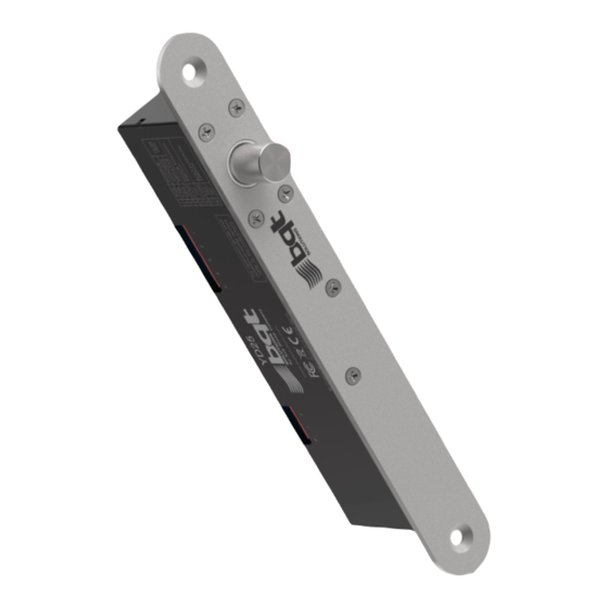
1. DESCRIPTION The YD25 is a solenoid operated dead bolting lock suited for commercial or residential doors. Being rated up to a million cycles makes this lock suitable for long term installations for single acting doors, where reliability is paramount. It is supplied with a matching strike plate and can be surface mounted with the aid of accessories or installed into a mortise for a concealed solution. -
Page 5: Strike Plate
3.2. Strike Plate 3.3. Long Strike Plate Available separately 3.4. Housing Available separately 3.5. Dress Plate Available separately 4. PRE-INSTALLATION ASSESSMENT 4.1. Mechanical The first decision regarding installation is whether the YD25 will be mortised or surface mounted to the door / door frame. -
Page 6: Electrical
Whichever method is chosen it is important that the lock and strike plate are aligned correctly. This is achieved when the top of the lock face plate aligns with the top of the strike plate. It is also important that when the door is closed the gap between the lock and strike plate does not exceed 6mm otherwise the lock will not sense the strikes position resulting in incorrect operation. - Page 7 5.1.1. Cutting the mortises Using the supplied lock dimensions a mortise is cut in the door frame that is suitable to house the lock. An appropriate sized mortise is then cut for the strike plate and hole to accept the bolt pin are drilled. The lock pin hole behind the strike plate needs to be free from debris and deep enough to allow the lock pin to fully extend when locked.
-
Page 8: Surface Installation
5.1.4. Checking the operation With the lock and strike installed and the wiring complete the door is closed to check alignment and operation. Surface installation 5.2. By using a YD25 housing the lock and/or strike plate can be secured to the door or door frame eliminating the need for cutting mortises. - Page 9 5.2.3. Fitting the lock Once wired, the lock is slid into the housing and secured in place with the M5 X 10 csk screws that were supplied with the lock. Make sure that the wiring integrity is maintained as the lock is screwed in place.
-
Page 10: Wiring
6. WIRING The YD25 is fitted with eight connectors; five are optional and provide monitoring of the lock pin and door positions. Control of the lock is achieved by using the remaining three wires however a reduced function two wire mode is available if desired. -
Page 11: Dip Switch Positions
6.4. Dip switch positions In addition to running the necessary wires for the desired mode, positioning the three dip switches located on the lock printed circuit board determines the operation. These are accessed by removing the cover. MARKINGS S1, S2 AND M ARE FOUND ON THE PRINTED CIRCUIT BOARD. Switches S1 and S2 are used to set the timed re-lock. -
Page 12: Specifications
8. SPECIFICATIONS MATERIALS Bolt Pin Stainless Steel (SS304), ø12.7mm, 16mm Extension Lock / Strike Plate Stainless Steel (SS304), 3mm Thick MECHANICAL Cycle life 1,000,000 normal operations Maximum Strike Gap Holding Force 10,000 newtons (1000kg) ELECTRICAL 12 – 24VDC ±15% Voltage at Lock Maximum Holding Current 160mA@12V 95mA@24V...
Need help?
Do you have a question about the BQT YD25 and is the answer not in the manual?
Questions and answers