Table of Contents
Advertisement
Quick Links
Advertisement
Table of Contents

Related Manuals for Datcon DT2500 Series


Summary of Contents for Datcon DT2500 Series
- Page 1 DT2500 IS Power Supply Operating manual...
-
Page 2: Table Of Contents
DT2500 Contents . About this document..............4 1.1. Function....................4 1.2. Target group..................4 1.3. Symbolism used .................. 4 2. For your safety................5 2.1. Authorized personal................5 2.2. Appropriate use ................... 5 2.3. Warning about misuse ................. 5 ... - Page 3 DT2500 8. Fault rectification..............15 8.1. Fault finding..................15 8.2. Repairing ................... 15 Dismounting................16 9.1. Dismounting procedure..............16 9.2. Disposal..................... 16 10. Appendix ................17 10.1. Technical specification..............17 10.2. ATEX certification ................19 20171220-V1...
-
Page 4: About This Document
DT2500 start 1. About this document 1.1. Function This operating instructions manual has all the information you need for quick set-up and safe operation of DT2500. Please read this manual before you start setup. 1.2. Target group This operating instructions manual is directed to trained personnel. The contents of this manual should be made available to these personnel and put into practice by them. -
Page 5: For Your Safety
For safety and warranty reasons, any internal work on the instruments must be carried out only by DATCON personnel. 2.2. Appropriate use The DT2500 is an intrinsically safe isolator / power supply product family. -
Page 6: Environmental Instructions
DT2500 2.7. Environmental instructions Protection of the environment is one of our most important duties. Please take note of the instructions written in the following chapters: • 3.6. Storage and transport • 9.2. Disposal 3. Product description 3.1. Delivery configuration The scope of delivery encompasses: Delivered items •... -
Page 7: Principle Of Operation
DT2500 3.3. Principle of operation The DT2500 IS Power Supply provide IS power for devices operate in Area of application zone 1 potentially explosive area. The power supplies are available in seven different output voltage and current variations (see table on the previous page). A front panel potentiometer makes possible to adjusting the output voltages, therefore any voltage of range the 5,8 - 24 V can be ensured. -
Page 8: Led Indicators
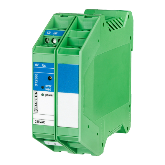
DT2500 3.5. LED indicators The following figure shows the front panel LED indicators: 1, "overload" indicator, light red, indicates the unit is overloaded. 2, "power" indicator, light green, indicates the output voltage is present. 3, P1 potentiometer to adjust the output voltage. 3.6. -
Page 9: Mounting
DT2500 4. Mounting 4.1. General instruction The instrument should be installing in the safe area in a cabinet with sufficient IP protection, where the operating conditions are in accordance with chapter 10.1. Technical specification, as described under the title: Operating conditions. The instruments are designed in housing for mounting on TS-35 rail. -
Page 10: Mounting Procedure
DT2500 4.3. Mounting procedure The following figure shows the mounting procedures (fixing on the rail): Mounting on the rail The mounting doesn’t need any tool. 1. Tilt the instrument according to the figure; put the instrument’s mounting hole onto the upper edge of the rail (figure step 1.). 2. -
Page 11: Connecting
DT2500 5. Connecting 5.1. Preparing the connection Always observe the following safety instructions: • When you are going to install instruments in hazardous area or install instruments which are connecting to instruments are working in hazardous area you should take note of the appropriate regulations, conformity and type approval certificates of the DT2500 and other instrument. -
Page 12: Connecting The Load Unit To The Device
DT2500 5.2. Connecting the load unit to the device The following figure shows the load unit connection to devices. Wiring plan, connecting the load (see also “Application example”) Be careful the polarity of the cables 1. Loosen terminal screws. 2. Insert the wire ends into the open terminals according to the wiring plan. -
Page 13: Connecting The Power Supply
DT2500 5.3. Connecting the power supply The following figure shows the power supply connection to devices. Wiring plan, connecting the power supply (see also “Application example”) Be careful the polarity of the cables The power supply should be operated only from 10 A overcurrent protection provided power network. -
Page 14: First Step
DT2500 6. First step 6.1. First step After turning on the power, the device ready to use. If the factory setting is good, you do not need configurable anything. If you want configurable your device, before the normal use you need follow the 7. -
Page 15: Fault Rectification
When the result of fault finding is that the DT2500 is defective call the manufacturer service department. 8.2. Repairing There is no user repairable part inside the instrument. In accordance with Chapter 2.1.: For safety and warranty reasons, any internal work on the instrument must be carried out by DATCON personnel. 20171220-V1... -
Page 16: Dismounting
DT2500 9. Dismounting 9.1. Dismounting procedure The following figure shows the dismounting procedures: Dismounting from the rail The dismounting procedure needs a screwdriver for slotted screws. 1. Before dismounting disconnect all wires. 2. Put the screwdriver end into the fixing assembly’s hole (figure step 1.). -
Page 17: Appendix
DT2500 10. Appendix 10.1. Technical specification Intrinsical safety data: Certification: BKI 15 ATEX 0023 X, BKI 15 ATEX 0023 X/1 Protection marking: II (2)G [Ex ib Gb] IIC/IIB (0 °C < Ta < +50 °C) 250 Veff Gyújtószikramentességre vonatkozó biztonsági adatok: Output Output Safety data... - Page 18 DT2500 Ambient conditions: Operating temperature rage: 0-50 °C Storage temperature range: -20 - +70 °C Relative humidity: 90% (max., non condensing) Place of installation Safe area, cabinet Installation: With 15 mm space Electromagnetic compatibility (EMC) according with the standard MSZ EN 61326-1:2013: Immunity: Industrial area -A- criterion @ U...
-
Page 19: Atex Certification
DT2500 start 10.2. ATEX certification 20171220-V1... - Page 20 DT2500 20171220-V1...
- Page 21 DT2500 20171220-V1...
- Page 22 DT2500 20171220-V1...
- Page 23 DT2500 20171220-V1...
- Page 24 DT2500 20171220-V1...
- Page 25 DT2500 20171220-V1...
- Page 26 DT2500 20171220-V1...
- Page 28 DT2500 20171220-V1...
Need help?
Do you have a question about the DT2500 Series and is the answer not in the manual?
Questions and answers