Table of Contents
Advertisement
Quick Links
Intrinsyc Open-Q™ 605 SBC User Guide and HW
Specification
[Document: ITC-01RND1384-UG-001 Version: 1.4]
Your use of this document is subject to and governed by those terms and conditions in the Intrinsyc Purchase an Open-Q™ 605 Development Kit
based on the Qualcomm QCS605 Processor and Software License Agreement for the Open-Q™ 605 Development Kit, which you or the legal entity
you represent, as the case may be, accepted and agreed to when purchasing an Open-Q™ Development Kit from Intrinsyc Technologies Corporation
("Agreement"). You may use this document, which shall be considered part of the defined term "Documentation" for purposes of the Agreement,
solely in support of your permitted use of the Open-Q™ 605 Development Kit under the Agreement. Distribution of this document is strictly
prohibited without the express written permission of Intrinsyc Technologies Corporation and its respective licensors, which they can withhold,
condition or delay in its sole discretion.
Intrinsyc is a trademark of Intrinsyc Technologies Corp., registered in Canada and other countries. QUALCOMM and Snapdragon™ are trademarks
of QUALCOMM Incorporated, registered in the United States and other countries. Other product and brand names used herein may be trademarks
or registered trademarks of their respective owners.
This document contains technical data that may be subject to U.S. and international export, re-export, or transfer ("export") laws. Diversion contrary
to U.S. and international law is strictly prohibited.
Advertisement
Table of Contents

Related Manuals for Intrinsyc Open-Q 605

Summary of Contents for Intrinsyc Open-Q 605
- Page 1 [Document: ITC-01RND1384-UG-001 Version: 1.4] Your use of this document is subject to and governed by those terms and conditions in the Intrinsyc Purchase an Open-Q™ 605 Development Kit based on the Qualcomm QCS605 Processor and Software License Agreement for the Open-Q™ 605 Development Kit, which you or the legal entity you represent, as the case may be, accepted and agreed to when purchasing an Open-Q™...
- Page 2 Intrinsyc Open-Q™ 605 SBC User Guide and HW Specification V. 1.4 IDENTIFICATION Intrinsyc Open-Q™ 605 SBC User Guide and HW Specification Document Title Document Number ITC-01RND1384-UG-001 Version Date Nov 26, 2019 History REVISION DATE DESCRIPTION PAGES Jan. 10, 2019 Initial Release Added battery, camera module, and LCD module Mar.
-
Page 3: Table Of Contents
Intrinsyc Open-Q™ 605 SBC User Guide and HW Specification V. 1.4 Table of Contents INTRODUCTION ................. 5 Purpose ......................5 Scope ......................5 Intended Audience ..................5 Acronyms and Abbreviations ..............5 Signal Name Suffix ..................6 REFERENCE DOCUMENTS ..............7 Applicable Documents ................ - Page 4 Intrinsyc Open-Q™ 605 SBC User Guide and HW Specification V. 1.4 5.2.1 Top Side ........................39 5.2.2 Bottom Side ......................39 SBC Mechanical Outline ................41 Top and Bottom Height Restrictions ............41 Weight ....................... 41 Labeling Information ................42 ACCESSORIES FOR THE 605 SBC............
-
Page 5: Introduction
1.2 Scope This document describes the features, functionality, and electrical and mechanical specifications of the Intrinsyc Open-Q™ 605 SBC. In addition to that, the document will also cover the following items: • Design guide for interfacing the included expansion interfaces 1.3 Intended Audience... -
Page 6: Signal Name Suffix
Intrinsyc Open-Q™ 605 SBC User Guide and HW Specification V. 1.4 Mobile Display Port MI2S Mobile Inter-IC Sound MICrophone MIPI Mobile Industry Processor Interface Multi-Purpose Pin Near Field Communication Printed Circuit Board PCIE Peripheral Component Interconnect Express Pulse-Width Modulation Radio Frequency... -
Page 7: Reference Documents
TITLE Intrinsyc Purchase and Software License Agreement Intrinsyc for the Open-Q™ 605 SBC 2.2 Reference Documents These documents are available to registered customers on the Intrinsyc support site: https://tech.intrinsyc.com REFERENCE TITLE Open-Q™ 605 SBC Schematics Open-Q™ 605 SBC Bill of Materials Open-Q™... -
Page 8: List Of Figures
Intrinsyc Open-Q™ 605 SBC User Guide and HW Specification V. 1.4 2.3 List of Figures Figure 1: Open-Q™ 605 SBC block diagram ................11 Figure 2: Open-Q™ 605 SBC label located at the bottom side of the SBC ........14 Figure 3: Debug UART pin locations .................... -
Page 9: List Of Tables
Intrinsyc Open-Q™ 605 SBC User Guide and HW Specification V. 1.4 List of Tables Table 3-1 - Open-Q™ 605 SBC functional specifications ............. 12 Table 3-2 – Debug UART connection ................... 15 Table 3-3 – Jumper settings for DC or battery power input ............16 Table 3-4 –... -
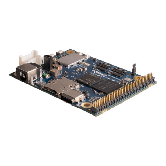
Page 10: Open-Q™ 605 Sbc Overview
Intrinsyc Open-Q™ 605 SBC User Guide and HW Specification V. 1.4 3. OPEN-Q™ 605 SBC OVERVIEW The Open-Q™ 605 SBC is a 50mm x 68mm production-ready, computing platform powered by the Qualcomm QCS605 system-on-chip. Figure 1, below, shows the block diagram of the SBC and this section describes the system features of the SBC. - Page 11 Intrinsyc Open-Q™ 605 SBC User Guide and HW Specification V. 1.4 Figure 1: Open-Q™ 605 SBC block diagram Copyright Intrinsyc Technologies Corporation...
-
Page 12: Open-Q™ 605 Sbc System Specifications
Intrinsyc Open-Q™ 605 SBC User Guide and HW Specification V. 1.4 3.1 Open-Q™ 605 SBC System Specifications The Open-Q™ 605 SBC platform encompasses the following hardware features: Table 3-1 - Open-Q™ 605 SBC functional specifications Subsystem / Feature Set Description... -
Page 13: Handling Precautions
Intrinsyc Open-Q™ 605 SBC User Guide and HW Specification V. 1.4 Subsystem / Feature Set Description Specification Connectors Multimedia MIPI CSI Two 4-lane CSI interfaces(CSI0 and D-PHY: 2.5 Gbps per lane Interfaces CSI2) C-PHY: ~17 Gbps (2.5 G symbols per trio per... -
Page 14: Getting Started
This section explains how to setup the Open-Q™ 605 SBC and start using it. 3.4.1 Registration To register the development kit and gain access to the Intrinsyc support site, please visit: http://tech.intrinsyc.com/account/register To proceed with registration, the development kit serial number is required. The serial number can be found on the label on the bottom side of the SBC. -
Page 15: How To Connect A Debug Uart
Intrinsyc Open-Q™ 605 SBC User Guide and HW Specification V. 1.4 3.4.2 How to Connect a Debug UART The debug UART port on the Open-Q™ 605 SBC can be found on the Expansion Connector (J3600) (for Expansion Connector pinout information, please refer to section 3.11). To access the debug UART, follow the pinouts in Table 3-2 below. -
Page 16: Powering Up The Sbc
SBC. Table 3-4 refers to the various jumper settings that are available for different boot options. Please note that the only boot from eMMC is supported by current BSP. Please contact Intrinsyc to enable different boot options such as boot from USB or SD card. - Page 17 Figure 5: Battery Connector (J3502) 3.5.1.1 Battery Pack Selection Intrinsyc does not sell nor ship battery packs with the Open-Q™ 605 SBC Development Kit. Users sourcing their own battery pack should note the absolute and operating input power ratings of the SBC listed below.
-
Page 18: Dc Power
Intrinsyc Open-Q™ 605 SBC User Guide and HW Specification V. 1.4 Table 3-5 – Open-Q™ 605 SBC Absolute Maximum Input Power Rating Parameter Units 6 (Steady State) Battery power input (VBATT) -0.5 7 (Transient, <10msec) 5V USB VBUS battery charger input voltage source (USB_VBUS) -0.3... -
Page 19: Sbc Connectors
Intrinsyc Open-Q™ 605 SBC User Guide and HW Specification V. 1.4 Figure 6: J3501 pin configuration for DC power Connect the supplied 12 VDC adaptor to DC Jack (J3500). Alternatively, DC power (5-15V) may be connected to the Expansion Connector. See section 3.11 for the Expansion Connector pinout table. -
Page 20: Dc Power Input (J3500)
Intrinsyc Open-Q™ 605 SBC User Guide and HW Specification V. 1.4 Domain Description Specification Usage MIPI Alliance Specification v1.00 for Camera Serial Interface Expansion For connecting external External GPIO connections 76 pin GPIO/power header connector peripherals To connect off board PCB 2.4 –... -
Page 21: Battery Connector (J3502)
Intrinsyc Open-Q™ 605 SBC User Guide and HW Specification V. 1.4 • PM670 is used for: ▪ Source various regulated power rails ▪ Battery charging. Please see section 3.8 below for additional information on battery support. ▪ Please note that support for battery charging over external charger is not implemented in the design. -
Page 22: Open-Q™ 605 Display Connector (J2700)
Intrinsyc Open-Q™ 605 SBC User Guide and HW Specification V. 1.4 Header J3502 (TE Connectivity: 2132415-4) can be mated with a few different plugs, such as TE 1969442-4, TE 1744417-4, and TE 2110992-4. Refer to the Section 3.5.1.1 for battery pack selection. -
Page 23: Camera Connectors (J2500, J2501)
Intrinsyc Open-Q™ 605 SBC User Guide and HW Specification V. 1.4 Signal Description DSI0_L1_N DSI Data Pair 1: Negative Channel DSI0_L1_P DSI Data Pair 1: Positive Channel Ground DSI0_CLK_N DSI Clock Pair: Negative Channel DSI0_CLK_P DSI Clock Pair: Positive Channel... - Page 24 Intrinsyc Open-Q™ 605 SBC User Guide and HW Specification V. 1.4 Table 3-10 – Camera 0 connector J2500 pin out Signal Description Ground Ground Ground Ground P2V8_VCM 2.8V Auto focus Voltage VCM_PWDN VCM Power down/Standby (Active Low) CAM0_CCI_SDA Camera I2C Data P1V8_DOVDD 1.8V IO Voltage...
- Page 25 Intrinsyc Open-Q™ 605 SBC User Guide and HW Specification V. 1.4 Signal Description Ground Ground Ground Ground P2V8_VCM 2.8V Auto focus Voltage VCM_PWDN VCM Power down/Standby (Active Low) CAM2_CCI_SDA Camera I2C Data P1V8_DOVDD 1.8V IO Voltage CAM2_CCI_SCL Camera I2C Clock P1V05_DVDD 1.05V Core VDD...
-
Page 26: Expansion Connector (J3600)
Intrinsyc Support site. In the event of pin-out difference(s) between this document and the SBC schematic, the SBC schematic shall take precedence. All signals are 1.8V tolerance except noted specifically. - Page 27 Intrinsyc Open-Q™ 605 SBC User Guide and HW Specification V. 1.4 Signal Signal DC_IN_JACK DC_IN_JACK LPI_QUP0_SDA APQ_GP119 LPI_QUP0_SCL VREG_L16A_3P0 LPI_QUP1_CS0_N SDM_DMIC_DATA1 LPI_QUP1_MOSI SDM_DMIC_CLK1 LPI_QUP1_CLK SDM_DMIC_DATA2 LPI_QUP1_MISO SDM_DMIC_CLK2 GP68_QUP8_L3 QUP12_DBG_UART_TX GP65_QUP8_L0 QUP12_DBG_UART_RX GP67_QUP8_L2 GP66_QUP8_L1 Copyright Intrinsyc Technologies Corporation...
- Page 28 Intrinsyc Open-Q™ 605 SBC User Guide and HW Specification V. 1.4 The table below outlines the pin information (primary and alternate functions) of the J3600 expansion connector: Table 3-13 – Summary of GPIOs Alternate Signal Default Function Description Description Functions...
- Page 29 Intrinsyc Open-Q™ 605 SBC User Guide and HW Specification V. 1.4 Alternate Signal Default Function Description Description Functions QDSS QDSS_TRACEDATA_14A QDSS trace data bit 14A GP44_QUP3_L3 QCS605: Configurable I/O : QUP_L3(3) Configurable I/O : QUP_L3(3) QUP 3, lane 3: QUP 3, lane 3: SPI_CS0...
- Page 30 Due to the nature of Qualcomm Low Power Island (LPI) architecture, changing LPI_GPIOs to an alternate function requires access to Qualcomm proprietary source code. Please contact Intrinsyc to make changes if an alternate function is needed. Table 3-14 – Summary of LPI_GPIOs...
- Page 31 Intrinsyc Open-Q™ 605 SBC User Guide and HW Specification V. 1.4 Alternate Signal Default Function Description Description Functions LPI_QUP1_CS0_N QCS605: LPI QUP 0, lane 3: SPI_CS0 LPI_QUP_L3(1) LPI QUP 1, lane 3: UART_RX LPI_QUP_L3(0) LPI QUP 1, lane 3: SPI_CS0...
- Page 32 Intrinsyc Open-Q™ 605 SBC User Guide and HW Specification V. 1.4 Table 3-15 – Summary of Audio Related Signals PIN # Signal Default Function Note CDC_HPH_L Headset Left Output Channel CDC_HPH_REF Headset Reference Connected to GND on REV2 SBC via R3610 (see document R-4).
- Page 33 Intrinsyc Open-Q™ 605 SBC User Guide and HW Specification V. 1.4 Table 3-17 – Summary of User Interface Signals PIN # Signal Default Function Note LED_RGB_RED RGB LED high-side current source for the red LED LED_RGB_BLUE RGB LED high-side current source for the blue LED...
-
Page 34: External Wi-Fi/Bt Antenna Port Specification (J3000, J3001)
Intrinsyc Open-Q™ 605 SBC User Guide and HW Specification V. 1.4 3.12 External Wi-Fi/BT Antenna Port Specification (J3000, J3001) Figure 12: WLAN/BT antenna connectors (J3000/J3001) The Open-Q™ 605 SBC provides WIFI and Bluetooth connectivity via the Qualcomm WCN3990 chipset. This provides 802.11 a/b/g/n/ac 2x2 MIMO, dual-band Wi-Fi, and Bluetooth 5.x. -
Page 35: Micro Sd Card (J2400)
Intrinsyc Open-Q™ 605 SBC User Guide and HW Specification V. 1.4 coax connector for GPS (J3100) is located on the bottom side of the SBC. Table 3-20 below outlines the mating connector that can be used to attach an external antenna to the GPS antenna connector. - Page 36 Intrinsyc Open-Q™ 605 SBC User Guide and HW Specification V. 1.4 A USB Type C connector (J3300) which is located on the top side of the Open-Q™ 605 SBC supports USB3.1, Display Port, Quick Charge 2.0/3.0, and Battery Charging 1.2. This connector is also the charge source for a Lithium Ion battery (see section 3.5.1 and 3.8 for information on...
-
Page 37: Electrical Specifications
Intrinsyc Open-Q™ 605 SBC User Guide and HW Specification V. 1.4 4. ELECTRICAL SPECIFICATIONS The input power to the SBC is provided by a power supply (battery or wall adapter) or an USB source, for battery charging purposes. All input power sources enter the PM670, which are then distributed via LDOs and switching power supplies. -
Page 38: Operating Temperature
Intrinsyc Open-Q™ 605 SBC User Guide and HW Specification V. 1.4 4.3 Operating Temperature The SBC operating temperature ratings listed below are based only on the component case temperature ratings of individual components used on the SBC. Users should consider the specific environmental conditions in which the final product is used in. -
Page 39: Mechanical Specifications
Intrinsyc Open-Q™ 605 SBC User Guide and HW Specification V. 1.4 5. MECHANICAL SPECIFICATIONS 5.1 Introduction This section describes the mechanical specifications of the Open-Q™ 605 SBC and provides information about the major components of the board and the various connectors used for connecting different peripherals. - Page 40 Intrinsyc Open-Q™ 605 SBC User Guide and HW Specification V. 1.4 Figure 17: Open-Q™ 605 SBC (bottom view) with pin 1 locations Copyright Intrinsyc Technologies Corporation...
-
Page 41: Sbc Mechanical Outline
Intrinsyc Open-Q™ 605 SBC User Guide and HW Specification V. 1.4 5.3 SBC Mechanical Outline The outer dimensions of the SBC are 68mm x 50mm. The SBC has 4 mounting holes, which are shown in Figure 18. Pin 1 and dimensions of the expansion connector (J3600) are also shown. -
Page 42: Labeling Information
Intrinsyc Open-Q™ 605 SBC User Guide and HW Specification V. 1.4 5.6 Labeling Information The Open-Q™ 605 SBC will have a serial number associated with the board. This serial number will be printed on a small label and placed on the board. The image below is an example of the label: Figure 19: Open-Q™... -
Page 43: Accessories For The 605 Sbc
6.1 Camera Module Intrinsyc offers the KLT IMX258 camera module accessory in two different lengths, 20mm and 100mm. The images shown here are of the 20mm version. The 100mm version attaches exactly the same way but has a longer flex cable section between the connector and the camera module. - Page 44 Intrinsyc Open-Q™ 605 SBC User Guide and HW Specification V. 1.4 If you purchased the camera module from Intrinsyc, the pin 2 location of the module will be clearly marked at the back side of the module. See picture in below...
- Page 45 Intrinsyc Open-Q™ 605 SBC User Guide and HW Specification V. 1.4 Figure 25: Camera module connected to CAM0 Figure 26: Camera module connected to CAM2 connector connector Due to the nature of the magnetic coil used for autofocus, it is necessary to keep a minimum separation distance of 10mm between two KLT camera modules.
-
Page 46: Lcd Display Accessory
Intrinsyc Open-Q™ 605 SBC User Guide and HW Specification V. 1.4 6.2 LCD Display Accessory Intrinsyc offers an optional LCD/touchscreen accessory for the 605 SBC, as seen in Figure 27 below. Figure 27: 605 SBC LCD/Touchscreen This section describes how to connect the LCD/touchscreen to your 605 SBC. - Page 47 Intrinsyc Open-Q™ 605 SBC User Guide and HW Specification V. 1.4 Step 2: Carefully lift the latch (black in colour) up. Figure 29: Display connector (latch opened) Step 3: Insert the cable into the connector, the blue stiffener on the flex cable should be facing up.
- Page 48 Intrinsyc Open-Q™ 605 SBC User Guide and HW Specification V. 1.4 Step 4: Close the latch by flipping the latch down as in step 1. Gently pull the cable. If the cable falls off, please repeat from step 1 again.
-
Page 49: Packaging And Shipping Information
Intrinsyc Open-Q™ 605 SBC User Guide and HW Specification V. 1.4 7. PACKAGING AND SHIPPING INFORMATION The Intrinsyc Open-Q™ 605 SBC is packaged individually in small anti-static bags and bubble- wrap bags for protection during shipping. They are then put into different sized boxes depending upon the quantity of the order. -
Page 50: Radio Certification Information
Intrinsyc Open-Q™ 605 SBC User Guide and HW Specification V. 1.4 8. RADIO CERTIFICATION INFORMATION The Intrinsyc Open-Q™ 605 SBC is expected to be certified with FCC and Industry Canada as a modular radio transmitter for WLAN and Bluetooth. When certification is complete, the FCC and Industry Canada ID numbers will be listed here. -
Page 51: Rohs / Reach Compliance
Intrinsyc Open-Q™ 605 SBC User Guide and HW Specification V. 1.4 9. ROHS / REACH COMPLIANCE The Intrinsyc Open-Q™ 605 SBC is expected to comply with the ROHS/REACH standard. When compliance is complete, information on the ROHS/REACH certificate will be listed here. -
Page 52: Company Contact
Intrinsyc Open-Q™ 605 SBC User Guide and HW Specification V. 1.4 10. COMPANY CONTACT For more information, support or sales, please contact us. Company Contact: Intrinsyc Technologies Corporation, 885 Dunsmuir St. 3rd Floor Vancouver, BC Canada V6C 1N5 (604) 801-6461 https://www.intrinsyc.com/...
Need help?
Do you have a question about the Open-Q 605 and is the answer not in the manual?
Questions and answers