Table of Contents
Advertisement
Quick Links
Advertisement
Table of Contents

Related Manuals for Datcon DT1362

Summary of Contents for Datcon DT1362
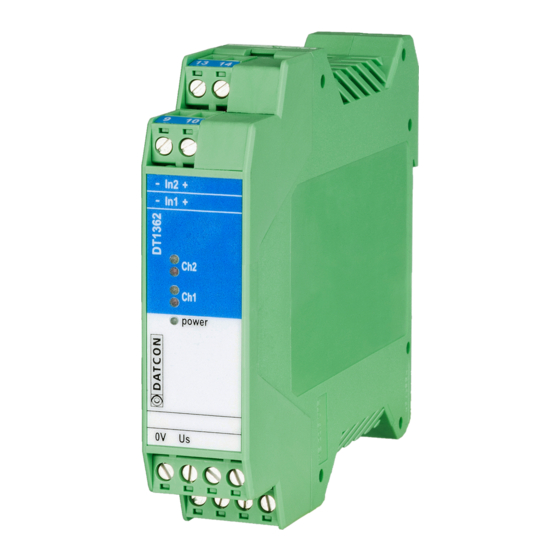
- Page 1 DT1362 Intrinsically Safe NAMUR / Contact Isolators Operating Instructions...
-
Page 2: Table Of Contents
DT1362 Contents 1. About this document .............4 1.1. Function ................... 4 1.2. Target group................4 1.3. Symbolism used............... 4 2. For your safety ...............5 2.1. Authorized personnel ............... 5 2.2. Appropriate use................ 5 2.3. Warning about misuse ............. 5 ... - Page 3 DT1362 7. Fault rectification ............18 7.1. Fault finding................18 7.2. Repairing................18 8. Dismounting ..............19 8.1. Dismounting procedure ............19 8.2. Disposal ................. 20 9. Appendix...............21 9.1. Technical specification ............21 9.2. Application example ............... 23 ...
-
Page 4: About This Document
1. About this document 1.1. Function This operating instructions manual has all the information you need for quick set-up and safe operation of DT1362. Please read this manual before you start setup. 1.2. Target group This operating instructions manual is directed to trained personnel. -
Page 5: For Your Safety
DATCON personnel (except setting DIL switches). 2.2. Appropriate use The DT1362 is a two channel intrinsically safe NAMUR / contact isolator. Detailed information on the application range is available in chapter 3. Product description. -
Page 6: Safety Information For Ex Areas
DT1362 2.6. Safety information for Ex areas Please note the Ex-specific safety information for installation and operation in Ex areas. 2.7. Environmental instructions Protection of the environment is one of our most important duties. Please take note of the instructions written in the following chapters: •... -
Page 7: Product Description
3.2. Principle of operation The DT1362 Intrinsically Safe NAMUR / Contact Isolator Area of application is a two channel unit enable two safe area load to be controlled by two proximity detector or switch, located in a potentially explosive area of zone 0 or zone 1. -
Page 8: Adjustment
The instrument works from a 19-29 VDC supply voltage. Power supply The power consumption is 1.1 W. 3.3. Adjustment The DT1362 operating modes can be set-up with two internal three element DIL switches. 20171206-V0... -
Page 9: Indicators
9.1 Technical specification, as described under the title: Environmental conditions. The packaging of DT1362 consist of environment-friendly, recyclable cardboard is used to protect the instrument against the impacts of normal stresses occurring during transportation. -
Page 10: Setting-Up The Operating Modes
DT1362 4. Setting-up the operating modes The operating modes can be set-up with the internal DIL switches (SW1, SW2). To reach the DIL switches the instrument housing shall be open. 4.1. Open the instrument housing The following figure shows how to open the instrument... -
Page 11: Setting Up Operating Modes
DT1362 The opening procedure needs a screwdriver for slotted screws 1. Push the upper opening lever of the housing with the screwdriver end slightly (figure step 1.). 2. Draw back the upper part of the housing back cover, to fix the opened position (figure step 2.) 3. -
Page 12: Close The Instrument Housing
DT1362 wire broken wire short → input output detection detection Operating modes reverse → Factory setting normal To use wire broken, wire short detection in a case of contact input see 6.2. Connecting the detectors or contacts to the inputs. -
Page 13: Mounting
DT1362 5. Mounting 5.1. General instructions The instrument should be install in the safe area in a cabinet with sufficient IP protection, where the operating conditions are in accordance with chapter 9.1 Technical specification, as described under the title: Operating conditions. -
Page 14: Mounting Procedure
DT1362 5.3. Mounting procedure The following figure shows the mounting procedures (fixing on the rail): Mounting on the rail The mounting doesn’t need any tools. 1. Tilt the instrument according to the figure; put the instrument’s mounting hole onto the upper edge of the rail (figure step 1.). -
Page 15: Connecting
DT1362 and other connecting instruments (e.g. detector). The connection must be carried out by trained and authorized personnel only! •... -
Page 16: Connecting The Detectors Or The Contacts To The Inputs
DT1362 6.2. Connecting the detectors or the contacts to the inputs. The following figure shows the wiring plan, connecting the detectors or the contacts to the inputs: Wiring plan, connecting the detectors or the contacts to the inputs (see also “Application example”) -
Page 17: Connecting The Relay Contacts And The Power Supply
DT1362 6.3. Connecting the relay contacts and the power supply The following figure shows the wiring plan, connecting the relay contacts and the power supply: Wiring plan, connecting the relay contacts and the power supply (see also “Application example”) 1. Loosen terminal screws. -
Page 18: Fault Rectification
If the channel works properly: the detector is defective. When the result of fault finding is that the DT1362 is defective call the manufacturer service department. 7.2. Repairing There is no user repairable part inside the instrument. -
Page 19: Dismounting
DT1362 8. Dismounting 8.1. Dismounting procedure The following figure shows the dismounting procedures: Dismounting from the rail The dismounting procedure needs a screwdriver for slotted screws. Pull out all the terminals: 1. Put the screwdriver into the slot between the terminal and the housing (figure step 1.). -
Page 20: Disposal
DT1362 8.2. Disposal According with the concerning EU directive, the manufacturer undertakes the disposal of the instrument that are manufactured by it and intended to be destroyed. Please deliver it in contamination-free condition to the site of the Manufacturer or to a specialized recycling company. -
Page 21: Appendix
Marking: II (1)G [Ex ia Ga] IIC/IIB (-20 °C ≤ Ta ≤ +50 °C) II (1)D [Ex ia Da] IIIC (-20 °C ≤ Ta ≤ +50 °C) Safety data: DT1362 Limit outputs safety data: 8.61 V 11.6 mA 24.96 mW 2 µF... - Page 22 DT1362 Ambient conditions: Operating temperature range: -20 °C ≤ Ta ≤ +50 °C Relative air humidity: 90% (max., non-condensing) Place of installation: safe area, cabinet Electromagnetic compatibility (EMC): accordance with the standard EN 61326-1 Immunity: Industrial area Noise emission: Group 1, Class B...
-
Page 23: Application Example
DT1362 9.2. Application example 20171206-V0... -
Page 24: Atex Certification
DT1362 9.3. ATEX Certification 20171206-V0... - Page 25 DT1362 20171206-V0...
- Page 26 DT1362 20171206-V0...
- Page 27 DT1362 20171206-V0...
- Page 28 DT1362 20171206-V0...
- Page 29 DT1362 20171206-V0...
- Page 30 DT1362 20171206-V0...
- Page 31 DT1362 20171206-V0...
- Page 32 DT1362 20171206-V0...
- Page 33 DT1362 20171206-V0...
- Page 34 DT1362 20171206-V0...
- Page 35 DT1362 20171206-V0...
Need help?
Do you have a question about the DT1362 and is the answer not in the manual?
Questions and answers