Advertisement
Quick Links
Advertisement

Summary of Contents for oddWires IoT-Bus
- Page 1 Documentation Release latest oddWires Mar 05, 2019...
- Page 3 8 Getting Started with Micro-Python 9 Getting Started with Moddable 10 Getting Started with MicroBlocks 11 Io 12 Proteus 13 JTAG 14 2.4” QVGA Touch Display 15 Motor 16 Relay 17 CAN Bus 18 LoRa 19 IoT-Bus Examples Index 20 IoT-Bus Blink Example...
- Page 4 30 IoT-Bus LED Thing 31 IoT-Bus LED Lamp Thing 32 IoT-Bus Relay Thing 33 IoT-Bus Relay Display-Touch Thing 34 IoT-Bus Window and Door Sensor Thing 35 IoT-Bus DHT11 Thing 36 IoT-Bus HC-SR04 Thing 37 IoT-Bus HC-SR501 PIR Thing 38 IoT-Bus Calculator Thing...
- Page 5 Documentation, Release latest IoT-Bus Introduction...
- Page 6 Documentation, Release latest IoT-Bus Introduction...
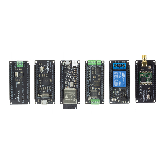
- Page 7 IoT-Bus Io and a version with a large prototyping area which enables a single-board IoT solution, the Proteus. The IoT-Bus is designed to be “plug and play” - the new range of oddWires open IoT-Bus boards use the Espressif ESP32 microprocessor (240Mhz, 32-bit, 4MB) for rapid, low-cost IoT development and deployment.
- Page 8 Documentation, Release latest Some IoT-Bus Boards 1.1 IoT-Bus System • Open Design • Low-cost • Plug and Play, Expandable • Powerful 240MHz, 32-bit Processor with 4Mb of Flash Memory • Multiple Form Factor Main Boards (Io, Proteus) • Connected in Many Ways (Wi-Fi, Bluetooth, BLE 4.0. LoRa and CAN Bus are available options) •...
- Page 9 This is why we are committed to supporting open standards and frameworks. We are partnering with mozilla to offer kits that can be used to quickly integrate with mozilla-iot. Watch this space for more details. We have also created many examples using iot-bus with mozilla-iot. See our examples on github.
- Page 10 Documentation, Release latest Fig. 1: Io 1.4 JTAG Both the Io and Proteus processor boards can accept a specially designed JTAG board offering hardware debugging. Our JTAG board is based on the FT232H and it enables comprehensive JTAG debugging support. You can use OpenOCD and GDB in combination to use it but our recommendation is to use PlatformIO.
- Page 11 2.8” as it has a crisper display at 320 x 240 res- olution slightly smaller size helps in IoT applications. Designed primarily for development use it has an IoT-Bus socket at the side. 1.5. 2.4” QVGA TFT Touch Display...
- Page 12 Documentation, Release latest 1.6 Two tional Con- nec- tiv- tions CAN Bus IoT- mod- fers transceiver that ables the onboard ESP32 CAN controller. You can connect the terminals to any required connection. LoRa This IoT- mod- uti- lizes Hope...
- Page 13 Documentation, Release latest often found. The RFM95W transceivers feature the LoRa long range modem that provides ultra-long range spread spectrum communication and high interference immunity whilst minimizing current consumption. Using Hope RF’s patented LoRa mod- tion tech- nique RFM95W...
- Page 14 Documentation, Release latest Fig. 5: CAN Bus 1.7 Two Controller Boards Relay This is an opto- isolated relay board driven by a single digital pin. It is a 110V, 10A maximum AC relay board in the IoT-Bus form factor.
- Page 15 Documentation, Release latest Fig. 7: Relay 1.8 Platforms Name Description Espres- Espressif Systems is a privately held fabless semiconductor company. They provide wireless communica- sif32 tions and Wi-Fi chips which are widely used in mobile devices and the Internet of Things applications.
- Page 16 Documentation, Release latest Chapter 1. IoT-Bus Overview...
- Page 17 CHAPTER IoT-Bus Pinout...
- Page 18 Documentation, Release latest Fig. 1: IoT-Bus Pinout Chapter 2. IoT-Bus Pinout...
- Page 19 Choosing a Platform and Framework One of the great things about IoT-Bus is that you’re free to choose from a large number of platforms and frameworks. You know that you want to create an IoT project but where do you start? In our view it very depends on what you know now.
- Page 20 So what would I do today? 1. Buy a kit from oddWires. 2. Choose a platform/framework. You can’t really go wrong. Your investment in IoT-Bus will work in every case and you can change your mind! 3. Get started with IoT-Bus and Mozilla IoT!
- Page 21 5. Plug in IoT-Bus Io. Open the iot-bus-blink example and run. Onboard LED should blink once a second. When you create a new PlatformIO application simply select the oddWires IoT-Bus Io as the board. This will also ensure you have the correct default debugger when using the IoT-Bus JTAG board.
- Page 22 Documentation, Release latest Chapter 4. Getting Started with PlatformIO...
- Page 23 Open Boards Manager from Tools > Board menu and install esp32 platform (select ESP32 Dev Module from Tools > Board menu after installation). 3. Run the Blink example Download the IoT-Bus examples from here. Then open the iot-bus-blink example and run. You’ll see the on-board LED blink once a second.
- Page 24 Documentation, Release latest Chapter 5. Getting Started with Arduino...
- Page 25 . It’s much easier using platformIO because it does all the hard work behind the scenes. However it maybe useful to see the steps involved. See Getting Started with Platformio for the easy way to use esp-idf. You can download or clone the IoT-Bus esp-idf examples from Github.
- Page 26 Documentation, Release latest Chapter 6. Getting Started with esp-idf...
- Page 27 This section of the documentation describes how to setup a gateway on a Raspberry Pi for the Mozilla-IoT platform. You will need a Raspberry Pi an SD Card and an IoT-Bus Io board. If you buy a Mozilla IoT Starter Kit from oddWires you will have everything you need.
- Page 28 Documentation, Release latest Choose to connect to a WiFi network and you’ll be prompted for the WiFi password. The gateway will connect to that network and then you’ll need to make sure you’re connected to that same network in order to continue setup. If you’re directly connected via ethernet you do not need to do this.
- Page 29 Documentation, Release latest You’ll be asked for an email address so you can reclaim your subdomain in future if necessary. You can also choose your own domain name if you don’t want to use the tunneling service, but you’ll need to generate your own SSL certificate and configure DNS yourself.
- Page 30 Documentation, Release latest You’ll then automatically be logged into the gateway and will be ready to start adding things. Note that the gateway’s web interface is a Progressive Web App that you can add to home-screen on your smartphone with Firefox. Now you should see this screen and the gateway is ready to add Things.
- Page 31 Documentation, Release latest 7.2 Adding Things You are now ready to add Things. To add devices to your gateway, click on the “+” icon at the bottom right of the screen. This will put all the attached adapters into pairing mode. Follow the instructions for your individual device to pair it with the gateway (this often involves pressing a button on the device while the gateway is in pairing mode).
- Page 32 Documentation, Release latest Chapter 7. Getting Started with Mozilla IoT...
- Page 33 CHAPTER Getting Started with Micro-Python MicroPython is a lean and efficient implementation of the Python 3 programming language that includes a small subset of the Python standard library and is optimized to run on micro-controllers and in constrained environments. You can find out more here.
- Page 34 Documentation, Release latest Chapter 8. Getting Started with Micro-Python...
- Page 35 CHAPTER Getting Started with Moddable You can find details on Getting Started with Moddable here.
- Page 36 Documentation, Release latest Chapter 9. Getting Started with Moddable...
- Page 37 CHAPTER Getting Started with MicroBlocks MicroBlocks is a new programming language inspired by Scratch that runs right inside micro-controller boards such as the micro:bit, the NodeMCU and many Arduino boards. The MicroBlocks system allows for dynamic, parallel and interactive programming, just like in Scratch, but with the twist of letting your projects run autonomously inside the board without being tethered to a computer.
- Page 38 Documentation, Release latest Chapter 10. Getting Started with MicroBlocks...
- Page 39 The battery is automatically charged in the USB is plugged in. A status light shows if it is charging or fully charged. All ESP32 pins bar the flash pins are exposed and available for your use. Buy it in the oddWires store. . .
- Page 40 11.2 Libraries This is not an exhaustive list of libraries available for IoT-Bus but it is a useful list of some of the libraries we have used and especially those we have used for examples. The license for each of the libraries can be found on each library’s GitHub page.
- Page 41 Documentation, Release latest 11.3 esp-idf-lib Components Component Description License Thread safety i2cdev I2C utilities ds1307 Driver for DS1307 RTC module ds3231 Driver for DS3231 high precision RTC module hmc5883l Driver for HMC5883L 3-axis digital compass onewire Bit-banging one wire driver...
- Page 42 Documentation, Release latest 11.6 Frameworks Name Description Arduino Wiring-based Framework allows writing cross-platform software to control devices attached to a wide range of Arduino boards to create all kinds of creative coding, interactive objects, spaces or physical duino experiences.
- Page 43 CHAPTER Proteus This board is larger and designed to make it possible to add your own circuitry to make a complete IoT solution on one board. It includes a dual-core 240 MHz ESP32 with WiFi and Bluetooth. You can use the WiFi both in station (device) mode and access point mode.
- Page 44 12.2 Libraries This is not an exhaustive list of libraries available for IoT-Bus but it is a useful list of some of the libraries we have used and especially those we have used for examples. The license for each of the libraries can be found on each library’s GitHub page.
- Page 45 Documentation, Release latest Name Board Framework Description webthing-arduino Io/Proteus Arduino Simple server for WiFi101, ESP8266, or ESP32 boards compliant with Mozilla’s proposed WoT API ESPAsyncWebServer Io/Proteus Arduino Asynchronous HTTP and WebSocket Server for ESP32 ArduinoJson Io/Proteus Arduino C++ JSON library for IoT. Simple and efficient.
- Page 46 Documentation, Release latest 12.4 Schematic 12.5 Platforms Name Description Espres- Espressif Systems is a privately held fabless semiconductor company. They provide wireless communica- sif32 tions and Wi-Fi chips which are widely used in mobile devices and the Internet of Things applications.
- Page 47 CHAPTER JTAG This IoT-Bus module provides JTAG debugging for the Proteus boards (can be used with other boards too, see wiring connections below). Both the Io and Proteus processor boards can accept a specially designed JTAG board offering hardware debugging.
- Page 48 Documentation, Release latest Buy it in the oddWires store. . . 13.1 PlatformIO Configuration You can configure the debugging tool using the debug_tool option in platformio.ini. If you are using an Io board (iot- busio in Platformio) or a Proteus board (iotbusproteus in PlatformIO) then you do not need to explicitly set debug_tool...
- Page 49 Documentation, Release latest 13.5 Frameworks Name Description Arduino Wiring-based Framework allows writing cross-platform software to control devices attached to a wide range of Arduino boards to create all kinds of creative coding, interactive objects, spaces or physical duino experiences.
- Page 50 Documentation, Release latest Chapter 13. JTAG...
- Page 51 We picked 2.4” over 2.8” as it has a crisper dis- play at 320 x 240 resolution and its slightly smaller size helps in IoT applications. Designed primar- ily for development use it has an IoT-Bus socket at the side for easy access. Here’s the back view:...
- Page 52 Documentation, Release latest Buy it in the oddWires store. . . 14.1 Pins Used IOT-Bus Pin Description DAT0 (SD Card) DAT1 (SD Card) SS (TFT) DAT2 (SD Card) DAT2 (SD Card) CLK (SD Card) CMD (SD) SS (Touch Screen)
- Page 53 IRQ is not used by the forked version of the XPT2046 library freeing up pin 17. The current versions of the IoT-Bus CAN Bus and LoRa modules cannot be used with this display.
- Page 54 Documentation, Release latest Chapter 14. 2.4” QVGA Touch Display...
- Page 55 CHAPTER Motor Buy it in the oddWires store. . . 15.1 Pins Used IOT-Bus Pin Description Power Ground...
- Page 56 Documentation, Release latest 15.2 Libraries Name Framework Description Adafruit_Motor_Shield_V2_Library Arduino Adafruit V2 Motor Shield library 15.3 Schematic Click image to enlarge. 15.4 Platforms Name Description Espres- Espressif Systems is a privately held fabless semiconductor company. They provide wireless communica- sif32 tions and Wi-Fi chips which are widely used in mobile devices and the Internet of Things applications.
- Page 57 Relay This is an opto-isolated relay board driven by a single digital pin. It is a 110V, 10A maximum AC relay board in the IoT-Bus form factor. Buy it in the oddWires store. . . 16.1 Pins Used IOT-Bus Pin...
- Page 58 Documentation, Release latest 16.2 Schematic Click image to enlarge. 16.3 Platforms Name Description Espres- Espressif Systems is a privately held fabless semiconductor company. They provide wireless communica- sif32 tions and Wi-Fi chips which are widely used in mobile devices and the Internet of Things applications.
- Page 59 CHAPTER CAN Bus Buy it in the oddWires store. . . 17.1 Pins Used IOT-Bus Pin Description CAN Bus RXD CAN Bus TXD Note: CAN Bus cannot be used at the same time as LoRa.
- Page 60 Documentation, Release latest 17.2 Libraries Name Framework Description Arduino-CAN Arduino Sandeep Mistry’s Arduino-CAN library Arduino-OBD2 Arduino Sandeep Mistry’s Arduino-OBD2 library requires Arduino-CAN 17.3 Schematic Click image to enlarge. 17.4 Platforms Name Description Espres- Espressif Systems is a privately held fabless semiconductor company. They provide wireless communica- sif32 tions and Wi-Fi chips which are widely used in mobile devices and the Internet of Things applications.
- Page 61 CHAPTER LoRa This IoT-Bus module utilizes the Hope RFM95 to offer low-cost, LoRa radio transmission and a Wi-Fi/LoRa gateway. It uses the correct 915 MHz rather than the 433 MHz european standard often found. The RFM95W transceivers fea- ture the LoRa long range modem that provides ultra-long range spread spectrum communication and high interference immunity whilst minimizing current consumption.
- Page 62 Potential Applications of the RF Transceiver Module RFM95W: • Automated Meter Reading. • Home and Building Automation. • Wireless Alarm and Security Systems. • Industrial Monitoring and Control • Long range Irrigation Systems Buy it in the oddWires store. . . Chapter 18. LoRa...
- Page 63 Documentation, Release latest 18.1 Pins Used IOT-Bus Pin Description DIO2 DIO1 LoRa RESET MISO MOSI DIO5(J) DIO4(J) DIO3(J) DIO0(J) Power Digital Ground Note: LoRa cannot be used at the same time as CAN Bus. 18.2 Libraries Name Framework Description...
- Page 64 Documentation, Release latest 18.5 Frameworks Name Description Arduino Wiring-based Framework allows writing cross-platform software to control devices attached to a wide range of Arduino boards to create all kinds of creative coding, interactive objects, spaces or physical duino experiences.
- Page 65 Demonstrates how to switch the relay on and off. LoRa How to send and receive data using LoRa. Motor How to control a stepper motor. Display Graphics and touch screen example. SD Card A test for the SD Card on the IoT-Bus Display.
- Page 66 Documentation, Release latest Chapter 19. IoT-Bus Examples Index...
- Page 67 CHAPTER IoT-Bus Blink Example This very simple example needs little explanation. The first line includes the Arduino framework. #include <arduino.h> The next line defined the GPIO of the pin of the onboard LED. #define LEDPin 5 This line sets the GPIO pin into output mode.
- Page 68 HIGH); // turn the LED on (HIGH is the voltage level) delay(1000); // wait for a second digitalWrite(LEDPin, LOW); // turn the LED off by making the voltage LOW delay(1000); // wait for a second Chapter 20. IoT-Bus Blink Example...
- Page 69 CHAPTER IoT-Bus Hello World Example This example shows the simplest way to create a web-server and uses a truly asynchronous approach. #include <WiFi.h> #include <AsyncTCP.h> #include <ESPAsyncWebServer.h> The WiFi library is required to be able to connect to WiFi. ESPAsyncWebServer provides the asynchronous web-server and AsyncTCP is required for an asynchronous TCP stack to support it.
- Page 70 AsyncWebServer server(80); void setup(){ Serial.begin(115200); WiFi.begin(ssid, password); while (WiFi.status() WL_CONNECTED) { delay(1000); Serial.println("Connecting to WiFi..."); Serial.println(WiFi.localIP()); server.on("/", HTTP_GET, [](AsyncWebServerRequest request){ request->send(200, "text/html", "<p>Hello World!</p>"); server.on("/html", HTTP_GET, [](AsyncWebServerRequest request){ request->send(200, "text/html", "<p>Some HTML!</p>"); server.begin(); void loop(){ Chapter 21. IoT-Bus Hello World Example...
- Page 71 CHAPTER IoT-Bus Touch Draw Example This example demonstrates the use of both the IoT-Bus Display and the touchscreen. In this example we are using a forked version of Bodmer’s TFT_eSPI library with User_Setup already setup for IoT-Bus Display which you can find here.
- Page 72 0, swatchWidth, swatchHeight, colors[i]); This fills a rectangle with a color. tft.setCursor(ts.getWidth()-swatchWidth 1.5, 3, 2); // x,y,font tft.setTextColor(TFT_WHITE); tft.print("Clear"); These lines position the cursor, set the text color and write some text at the cursor position. Chapter 22. IoT-Bus Touch Draw Example...
- Page 73 Documentation, Release latest (ts.touched()) Use the touched function to find out whether the display has been touched. TS_Point p ts.getMappedPoint(); This will get an x, y and z value. Although it is not used here you could see how hard the press was by comparing the z value.
- Page 74 // Read the current X and Y axis as mapped co-ordinates at the last touch time TS_Point p ts.getMappedPoint(); // mapped pixel Serial.print(p.x); Serial.print(","); Serial.println(p.y); // Detect paint brush color change (p.y < swatchHeight (continues on next page) Chapter 22. IoT-Bus Touch Draw Example...
- Page 75 Documentation, Release latest (continued from previous page) (p.x swatchWidth > // Clear the screen to current color tft.fillRect(0, swatchHeight, ts.getWidth(), ts.getHeight()-1, color); Serial.println("clear screen to current color"); else color colors[p.x swatchWidth]; // Update the current color in the clear box tft.fillRect(ts.getWidth()
- Page 76 Documentation, Release latest Chapter 22. IoT-Bus Touch Draw Example...
- Page 77 CHAPTER IoT-Bus Relay Example It is very easy to use the IoT-Bus relay. Simply set the relay pin high to turn on the relay as the relay is active high. The full example is shown below. Turns the Relay on for one second, then off for one second, repeatedly.
- Page 78 Documentation, Release latest Chapter 23. IoT-Bus Relay Example...
- Page 79 CHAPTER IoT-Bus CAN Bus Example These two examples work together using Sandeep Mistry’s excellent arduino-CAN library which can be found here. 24.1 CAN Bus Send #include <CAN.h> void setup() { Serial.begin(115200); // start the CAN bus at 1000 kbps (!CAN.begin(1000E3)) { Serial.println("Starting CAN...
- Page 80 CAN.endPacket(); Serial.println("done"); delay(1000); // send extended packet: id is 29 bits, packet can contain up to 8 bytes of data Serial.print("Sending extended packet ... "); CAN.beginExtendedPacket(0xabcdef); CAN.write('w'); CAN.write('o'); CAN.write('r'); CAN.write('l'); CAN.write('d'); CAN.endPacket(); Serial.println("done"); delay(1000); Chapter 24. IoT-Bus CAN Bus Example...
- Page 81 Documentation, Release latest 24.2 CAN Bus Receive #include <CAN.h> void setup() { Serial.begin(115200); while (!Serial); Serial.println("CAN Receiver"); // start the CAN bus at 1000 kbps (!CAN.begin(1000E3)) { Serial.println("Starting CAN failed!"); while (1); Include the CAN Bus library and start it up at 1Mbps.
- Page 82 Serial.print("packet with id 0x"); Serial.print(CAN.packetId(), HEX); (CAN.packetRtr()) { Serial.print(" and requested length "); Serial.println(CAN.packetDlc()); else Serial.print(" and length "); Serial.println(packetSize); // only print packet data for non-RTR packets while (CAN.available()) { Serial.print((char)CAN.read()); Serial.println(); Serial.println(); Chapter 24. IoT-Bus CAN Bus Example...
- Page 83 #define SS #define RESET 17 counter void setup() { LoRa.setPins(SS, RESET, DIO0); These lines include the libraries required and define the DIO0, SS and RESET pins required to use the IoT-BUs LoRa board. (!LoRa.begin(915E6)) { Serial.println("Starting LoRa failed!"); while (1);...
- Page 84 #define DIO0 35 #define SS #define RESET 17 counter void setup() { LoRa.setPins(SS, RESET, DIO0); These lines include the libraries required and define the DIO0, SS and RESET pins required to use the IoT-BUs LoRa board. Chapter 25. IoT-Bus LoRa Example...
- Page 85 Documentation, Release latest (!LoRa.begin(915E6)) { Serial.println("Starting LoRa failed!"); while (1); These lines attempt to start LoRa and will go no further if failure. // try to parse packet packetSize LoRa.parsePacket(); (packetSize) { // received a packet Serial.print("Received packet '");...
- Page 86 Documentation, Release latest (continued from previous page) Serial.print((char)LoRa.read()); // print RSSI of packet Serial.print("' with RSSI "); Serial.println(LoRa.packetRssi()); Chapter 25. IoT-Bus LoRa Example...
- Page 87 CHAPTER IoT-Bus Motor Example This example use the Adafruit_Motorshield library which you can find here to control a stepper motor on the IoT-Bus Motor board. This is a test sketch for the iot-bus motor board #include <Wire.h> #include <Adafruit_MotorShield.h> #include "utility/Adafruit_MS_PWMServoDriver.h"...
- Page 88 BACKWARD, INTERLEAVE); Serial.println("Microstep steps"); myMotor->step(50, FORWARD, MICROSTEP); myMotor->step(50, BACKWARD, MICROSTEP); Move the stepper motor forward and backward in different ways. The full example is shown beow. This is a test sketch for the iot-bus motor board #include <Wire.h> #include <Adafruit_MotorShield.h> #include "utility/Adafruit_MS_PWMServoDriver.h"...
- Page 89 CHAPTER IoT-Bus SD_MMC Card Example This example show how to test an SD Card on the IoT-Bus Display board. if(!SD_MMC.begin("/sdcard")){ Serial.println("Card Mount Failed"); return; uint8_t cardType SD_MMC.cardType(); if(cardType CARD_NONE){ Serial.println("No SD_MMC card attached"); return; Serial.print("SD_MMC Card Type: "); if(cardType CARD_MMC){ Serial.println("MMC");...
- Page 90 These lines list, create and remove directories. After that a file is written, data appended and read. If “/foo.text” exists it is deleted and “/hello.txt” is renamed. Then it is read. Lastly some read and write timings are performed. This is a test of the iot-bus SD_MMC #include "FS.h"...
- Page 91 Documentation, Release latest (continued from previous page) else Serial.println("mkdir failed"); void removeDir(fs::FS &fs, const char path){ Serial.printf("Removing Dir: %s\n", path); if(fs.rmdir(path)){ Serial.println("Dir removed"); else Serial.println("rmdir failed"); void readFile(fs::FS &fs, const char path){ Serial.printf("Reading file: %s\n", path); File file fs.open(path);...
- Page 92 Serial.println("Failed to open file for reading"); file fs.open(path, FILE_WRITE); if(!file){ Serial.println("Failed to open file for writing"); return; size_t start millis(); for(i=0; i<2048; i++){ file.write(buf, 512); (continues on next page) Chapter 27. IoT-Bus SD_MMC Card Example...
- Page 93 Documentation, Release latest (continued from previous page) millis() start; Serial.printf("%u bytes written for %u ms\n", 2048 512, end); file.close(); void setup(){ Serial.begin(115200); if(!SD_MMC.begin("/sdcard")){ Serial.println("Card Mount Failed"); return; uint8_t cardType SD_MMC.cardType(); if(cardType CARD_NONE){ Serial.println("No SD_MMC card attached"); return; Serial.print("SD_MMC Card Type: ");...
- Page 94 Documentation, Release latest Chapter 27. IoT-Bus SD_MMC Card Example...
- Page 95 IoT-Bus Mozilla IoT Examples These examples are designed to run on IoT-Bus boards by oddWires. In each case, they demonstrate how to create a mozilla-iot “thing” and expose it through the mozilla-iot gateway running on a raspberry pi on the same Wi-Fi network.
- Page 96 This example creates a Thing that enables the status and brightness of the built-in LED on GPIO5 to be set through the mozilla-iot domain. DHT11 Thing This example creates a Thing that exposes temperature and humidity properties and also displays the temperature locally. Chapter 28. IoT-Bus Mozilla IoT Examples...
- Page 97 Relay Thing This example uses an IoT-Bus relay board together with an IoT-Bus Io processor to expose the relay status and to enable the user to change through your mozilla-iot domain.
- Page 98 Documentation, Release latest Chapter 28. IoT-Bus Mozilla IoT Examples...
- Page 99 CHAPTER IoT-Bus LED Touch Thing #include <Arduino.h> #include <Thing.h> #include <WebThingAdapter.h> Simple binary sensor example using ESP32 capacitive touch input This example code is in the public domain. //TODO: Hardcode your wifi credentials here (and keep it private) const char ssid "..";...
- Page 100 OUTPUT); // declare LED as output void loop() { touchRead(T0); // get value using T0 / GPIO4 Serial.println(val); (val < threshold){ sensorValue.boolean true; digitalWrite(ledPin, HIGH); else{ sensorValue.boolean false; digitalWrite(ledPin, LOW); touched.setValue(sensorValue); adapter->update(); delay(300); Chapter 29. IoT-Bus LED Touch Thing...
- Page 101 CHAPTER IoT-Bus LED Thing / ** * Simple server compliant with Mozilla's proposed WoT API * Originally based on the HelloServer example * Tested on ESP8266, ESP32, Arduino boards with WINC1500 modules (shields or * MKR1000) * This Source Code Form is subject to the terms of the Mozilla Public * License, v.
- Page 102 Serial.println(WiFi.localIP()); adapter WebThingAdapter("w25", WiFi.localIP()); led.addProperty(&ledOn); adapter->addDevice(&led); adapter->begin(); Serial.println("HTTP server started"); Serial.print("http://"); Serial.print(WiFi.localIP()); Serial.print("/things/"); Serial.println(led.id); void loop(void){ adapter->update(); bool ledOn.getValue().boolean; digitalWrite(ledPin, on HIGH : LOW); // active high led lastOn) { Serial.print(led.id); Serial.print(": "); Serial.println(on); lastOn Chapter 30. IoT-Bus LED Thing...
- Page 103 CHAPTER IoT-Bus LED Lamp Thing / ** * Simple server compliant with Mozilla's proposed WoT API * Originally based on the HelloServer example * Tested on ESP8266, ESP32, Arduino boards with WINC1500 modules (shields or * MKR1000) * This Source Code Form is subject to the terms of the Mozilla Public * License, v.
- Page 104 // Wait for connection while (WiFi.status() WL_CONNECTED) { delay(500); Serial.print("."); Serial.println(""); Serial.print("Connected to "); Serial.println(ssid); Serial.print("IP address: "); Serial.println(WiFi.localIP()); adapter WebThingAdapter("led-lamp", WiFi.localIP()); lamp.addProperty(&lampOn); lamp.addProperty(&lampLevel); adapter->addDevice(&lamp); adapter->begin(); Serial.println("HTTP server started"); #ifdef analogWriteRange analogWriteRange(255); #endif (continues on next page) Chapter 31. IoT-Bus LED Lamp Thing...
- Page 105 Documentation, Release latest (continued from previous page) void loop(void){ adapter->update(); (lampOn.getValue().boolean) { level map(lampLevel.getValue().number, 0, 100, 0, 255); Serial.println(lampLevel.getValue().number); ledcAnalogWrite(LEDC_CHANNEL_0, level); analogWrite(lampPin, level); else ledcAnalogWrite(LEDC_CHANNEL_0, 0); analogWrite(lampPin, 255);...
- Page 106 Documentation, Release latest Chapter 31. IoT-Bus LED Lamp Thing...
- Page 107 CHAPTER IoT-Bus Relay Thing #include <Arduino.h> #include "Thing.h" #include "WebThingAdapter.h" Turns on/off a relay using MOZ IoT. This example code is in the public domain. //TODO: Hard-code your WiFi credentials here (and keep it private) const char ssid ".."; const...
- Page 108 WebThingAdapter("adapter", WiFi.localIP()); relay.addProperty(&relayOn); adapter->addDevice(&relay); adapter->begin(); Serial.println("HTTP server started"); Serial.print("http://"); Serial.print(WiFi.localIP()); Serial.print("/things/"); Serial.println(relay.id); void loop() { // update status adapter->update(); bool relayOn.getValue().boolean; digitalWrite(relayPin, on HIGH : LOW); // active high lastOn) { Serial.print(relay.id); Serial.print(": "); Serial.println(on); lastOn Chapter 32. IoT-Bus Relay Thing...
- Page 109 ".."; const char password ".."; const relayPin // IoT-Bus relay 16 or 17 supported. If using touchscreen then relay must be on GPIO17 and PENIRQ not used. TFT OK either way. Graphics and Touch #include <TFT_eSPI.h> #include <XPT2046_Touchscreen.h> // We use modified version that maps from raw to...
- Page 110 Serial.print("Connected to "); Serial.println(ssid); Serial.print("IP address: "); Serial.println(WiFi.localIP()); // Turn on display pinMode(33, OUTPUT); // turn on the IoT-Bus Display digitalWrite(33, HIGH); // Start display and draw plug tft.begin(); tft.setRotation(1); (continues on next page) Chapter 33. IoT-Bus Relay Display-Touch Thing...
- Page 111 Documentation, Release latest (continued from previous page) // background tft.fillScreen(ILI9341_MOZCYAN); // closest 16 bit color to MOZ IOT // draw initial state drawPlug(false); // start the touch screen ts.begin(); // Initialize MOZ IoT thing adapter WebThingAdapter("adapter", WiFi.localIP()); relay.addProperty(&relayOn); adapter->addDevice(&relay);...
- Page 112 #define TEXT_O_Y 192 #define TEXT_O_RADIUS 13 #define TEXT_HEIGHT 25 #define STROKE_WIDTH 5 #define TEXT_2_X 160 #define TEXT_2_Y 180 #define TEXT_WIDTH 15 #define TEXT_3_X 180 #define TEXT_3_Y 180 #define OFFSET 8 (continues on next page) Chapter 33. IoT-Bus Relay Display-Touch Thing...
- Page 113 Documentation, Release latest (continued from previous page) if(on){ // O tft.fillCircle(TEXT_O_X+OFFSET, TEXT_O_Y, TEXT_O_RADIUS, textColor); tft.fillCircle(TEXT_O_X+OFFSET, TEXT_O_Y, TEXT_O_RADIUS-STROKE_WIDTH, bgColor); // N tft.fillRect(TEXT_2_X+OFFSET, TEXT_2_Y, STROKE_WIDTH, TEXT_HEIGHT, textColor); tft.fillRect(TEXT_2_X+TEXT_WIDTH+OFFSET, TEXT_2_Y, STROKE_WIDTH, TEXT_HEIGHT, textColor); for(int i=0;i<STROKE_WIDTH;i++){ tft.drawLine(TEXT_2_X+i+OFFSET, TEXT_2_Y, TEXT_2_X+TEXT_WIDTH+i+OFFSET, TEXT_ 2_Y+TEXT_HEIGHT, textColor); else{ // O tft.fillCircle(TEXT_O_X, TEXT_O_Y, TEXT_O_RADIUS, textColor);...
- Page 114 Documentation, Release latest Chapter 33. IoT-Bus Relay Display-Touch Thing...
- Page 115 CHAPTER IoT-Bus Window and Door Sensor Thing #include <Arduino.h> #include <Thing.h> #include <WebThingAdapter.h> Simple binary sensor example using ESP32 capacitive touch input This example code is in the public domain. //TODO: Hardcode your wifi credentials here (and keep it private)
- Page 116 // declare LED as output void loop() { digitalRead(sensorPin); // get value Serial.println(val); (val LOW){ sensorValue.boolean false; // pulled to GND digitalWrite(ledPin, LOW); else{ sensorValue.boolean true; // pullup active digitalWrite(ledPin, HIGH); openProperty.setValue(sensorValue); adapter->update(); delay(300); Chapter 34. IoT-Bus Window and Door Sensor Thing...
- Page 117 CHAPTER IoT-Bus DHT11 Thing #include <arduino.h> (continues on next page)
- Page 118 * Reads temperature from DHT11 sensor * @return bool true if temperature could be aquired false if aquisition failed TempAndHumidity newValues; bool getTemperature() { // Reading temperature for humidity takes about 250 milliseconds! (continues on next page) Chapter 35. IoT-Bus DHT11 Thing...
- Page 119 Documentation, Release latest (continued from previous page) // Sensor readings may also be up to 2 seconds 'old' (it's a very slow sensor) newValues dht.getTempAndHumidity(); // Check if any reads failed and exit early (to try again). (dht.getStatus() 0) { Serial.println("DHT11 error status: "...
- Page 120 Serial.begin(115200); dht.setup(dhtPin, DHTesp::DHT11); // Turn on display pinMode(33, OUTPUT); // turn on the IoT-Bus Display digitalWrite(33, HIGH); // Start display and clear display.begin(); display.fillScreen(ILI9341_BLACK); // Start WiFi WiFi.mode(WIFI_STA); WiFi.begin(ssid, password); Serial.println(""); // Wait for connection while (WiFi.status()
- Page 121 Documentation, Release latest (continued from previous page) // Initialize MOZ IoT thing adapter WebThingAdapter("multilevelsensor", WiFi.localIP()); dht11.addProperty(&temperature); dht11.addProperty(&humidity); adapter->addDevice(&dht11); adapter->begin(); loop() { void getTemperature(); current String(dht.toFahrenheit(newValues.temperature)) "°F " String(newValues.humidity) "%"; (current last){ displayString(last, ILI9341_BLACK); // clear old text by writing it black displayString(current, ILI9341_WHITE);...
- Page 122 Documentation, Release latest Chapter 35. IoT-Bus DHT11 Thing...
- Page 123 CHAPTER IoT-Bus HC-SR04 Thing Arduino framework #include <arduino.h> MOZ IoT (continues on next page)
- Page 124 // current and last values of text void displayString(const String& str, color) { str.length()+1; strWidth textWidth; strHeight textHeight; scale width strWidth; width (strWidth scale height (strHeight scale display.setFreeFont(&FreeSans18pt7b); display.setRotation(1); display.setTextColor(color); display.setTextSize(scale); display.setCursor(x, y); display.println(str); (continues on next page) Chapter 36. IoT-Bus HC-SR04 Thing...
- Page 125 // Start serial monitor - make sure same speed as monitor Serial.begin (115200); // HC-SR04 pins pinMode(trigPin, OUTPUT); pinMode(echoPin, INPUT); // Turn on display pinMode(33, OUTPUT); // turn on the IoT-Bus Display digitalWrite(33, HIGH); // Start display and clear display.begin(); display.fillScreen(ILI9341_BLACK); // Start WiFi WiFi.mode(WIFI_STA);...
- Page 126 ILI9341_WHITE); // write the new value measurement.number inches; distance.setValue(measurement); adapter->update(); // update the MOZ IoT thing last current; // remember the last write to be able to clear it delay(500); // vary to suit Chapter 36. IoT-Bus HC-SR04 Thing...
- Page 127 CHAPTER IoT-Bus HC-SR501 PIR Thing #include <Arduino.h> Simple motion sensor example using HC-S501 (continues on next page)
- Page 128 // declare LED as output pinMode(inputPin, INPUT); // declare sensor as input void loop(){ digitalRead(inputPin); // read input value (val HIGH) { // check if the input is HIGH (sensorOn.getValue().boolean true) { (continues on next page) Chapter 37. IoT-Bus HC-SR501 PIR Thing...
- Page 129 Documentation, Release latest (continued from previous page) // Turned on Serial.println("Motion detected!"); // Update on the output change, not state sensorValue.boolean true; digitalWrite(ledPin, HIGH); else (sensorOn.getValue().boolean true){ // Turned off Serial.println("Motion ended!"); // Update on the output change, not state sensorValue.boolean...
- Page 130 Documentation, Release latest Chapter 37. IoT-Bus HC-SR501 PIR Thing...
- Page 131 CHAPTER IoT-Bus Calculator Thing / * ______Import Libraries_______ * / #include "TFT_eSPI.h" // Hardware-specific library #include "colors.h" // extended colors #include <XPT2046_Touchscreen.h> #include <FS.h> #include <WiFi.h> MOZ IoT #include <Thing.h> #include <WebThingAdapter.h> / * ______End of Libraries_______ * / WiFi ssid and password...
- Page 132 // redraw return true; return false; private: TFT_eSPI& tft; uint16_t 0, y 0, width 240, height 320, color TFT_WHITE, bgColor TFT_BLACK; uint8_t type; // user type uint8_t alignment MIDDLE; String text ""; (continues on next page) Chapter 38. IoT-Bus Calculator Thing...
- Page 133 Documentation, Release latest (continued from previous page) / * ____Calibration values TFT TS_____ * / #define TS_MINX 256 #define TS_MINY 274 #define TS_MAXX 3632 #define TS_MAXY 3579 / * ______End of Calibration______ * / class Calculator{ private: TFT_eSPI& tft;...
- Page 134 Button(tft); buttons[(j 4)+i]->setRect( i, resultBoxHeight j), buttonWidth, buttonHeight ); buttons[(j 4)+i]->setBgColor(buttonColors[j][i]); buttons[(j 4)+i]->setText(String(symbol[j][i]), TFT_BLACK); buttons[(j 4)+i]->setType(buttonTypes[j][i]); buttons[(j 4)+i]->draw(); // Handle each button void handleButton(Button button){ uint8_t type button->getType(); Serial.println(type); switch(type){ default: (continues on next page) Chapter 38. IoT-Bus Calculator Thing...
- Page 135 Documentation, Release latest (continued from previous page) case NUM: handleNumber(button); displayResult(); Serial.println("number"); break; case CLEAR: Serial.println("clear"); Accumulator=Num1=Num2=0; displayResult(); break; case EQUALS: handleEquals(button); displayResult(); Serial.println("="); break; case MULTIPLY: case DIVIDE: case ADD: case SUBTRACT: action button->getType(); Serial.println("function"); Num1 Accumulator; Accumulator function button->getText();...
- Page 136 //Use serial monitor for debugging Serial.println("Starting Caclulator"); ts.setSize(240,320); // set width, height ts.begin(); // Turn on display pinMode(33, OUTPUT); // turn on the IoT-Bus Display digitalWrite(33, HIGH); // Start WiFi WiFi.mode(WIFI_STA); (continues on next page) Chapter 38. IoT-Bus Calculator Thing...
- Page 137 Documentation, Release latest (continued from previous page) WiFi.begin(ssid, password); Serial.println(""); // Wait for connection while (WiFi.status() WL_CONNECTED) { delay(500); Serial.print("."); Serial.println(""); Serial.print("Connected to "); Serial.println(ssid); Serial.print("IP address: "); Serial.println(WiFi.localIP()); // Initialize MOZ IoT thing adapter WebThingAdapter("textdisplayer", WiFi.localIP()); value.string &iotbus;...
- Page 138 Documentation, Release latest Chapter 38. IoT-Bus Calculator Thing...
- Page 139 IoT-Bus ESP32 processor and the LED lamp. We will see how to get the working on their own and then use the Mozilla IoT Rules engine to control the on-board LED on the IoT-BUs IO board to reflect the state of the capacitive switch.
- Page 140 Documentation, Release latest Chapter 39. IoT-Bus Mozilla IoT Tutorials...
- Page 141 GitHub. This tutorial requires an IoT-Bus Io ESP32 processor board. Once running you will be able to control the on-board LED on the IoT-Bus Io using the Mozilla-IoT browser interface. You will need to have installed the Mozilla-IoT gateway on a Raspberry PI as described here.
- Page 142 Documentation, Release latest adapter WebThingAdapter("w25", WiFi.localIP()); const char ledTypes[] {"OnOffSwitch", "led", nullptr}; ThingDevice led("LED", "LED", ledTypes); ThingProperty ledOn("On", "", BOOLEAN, "OnOffProperty"); These are the the lines of code that define the Mozilla-IoT Thing and its properties. const char ledTypes[] {"OnOffSwitch", "led", nullptr};...
- Page 143 Documentation, Release latest adapter->update(); ledOn.getValue().boolean; bool digitalWrite(ledPin, on HIGH : LOW); // active high led lastOn) { Serial.print(led.id); Serial.print(": "); Serial.println(on); lastOn In the loop function, the latest state of the adapter is obtained. If we had changed the state of the LED locally we would need to call the update function to have it reflected through the gateway.
- Page 144 Documentation, Release latest The LED should respond to you turning it off and on in the Mozilla IoT interface! There are lots more examples in the Github file you downloaded or cloned. The full code is shown below. / **...
- Page 145 Documentation, Release latest (continued from previous page) void setup(void){ pinMode(ledPin, OUTPUT); digitalWrite(ledPin, HIGH); Serial.begin(115200); Serial.println(""); Serial.print("Connecting to \""); Serial.print(ssid); Serial.println("\""); #if defined(ESP8266) || defined(ESP32) WiFi.mode(WIFI_STA); #endif WiFi.begin(ssid, password); Serial.println(""); // Wait for connection bool blink true; while (WiFi.status() WL_CONNECTED) { delay(500);...
- Page 146 Documentation, Release latest Chapter 40. LED Thing Tutorial...
- Page 147 This tutorial requires an IoT-Bus Io ESP32 processor board and a simpler jumper lead connected to GPIO4. Once running you will be able to use a capacitive switch on a GPIO pin on the IoT-Bus Io to be exposed to the Mozilla- IoT browser interface.
- Page 148 Documentation, Release latest WebThingAdapter adapter; This defines a pointer to a Mozilla-IoT adapter which is set when a new adapter is created in setup as below. adapter WebThingAdapter("adapter", WiFi.localIP()); const char sensorTypes[] {"binarySensor", nullptr}; ThingDevice touch("Touch", "ESP32 Touch Input", sensorTypes);...
- Page 149 Documentation, Release latest (continued from previous page) touched.setValue(sensorValue); adapter->update(); delay(300); Note: sensorValue must not be allocated on the stack. It must be in a location that can be referred to asynchronously, so we have allocated it globally for simplicity. You’ll get a memory trap if you allocate it on the stack.
- Page 150 Documentation, Release latest The onboard LED will light when the wire is touched and turn off when the wire is released. At the same time the Mozilla IoT interface will reflect the status of the wire whether touched or not. There are lots more examples in...
- Page 151 Documentation, Release latest (continued from previous page) Serial.begin(115200); // Start WiFi WiFi.mode(WIFI_STA); WiFi.begin(ssid, password); Serial.println(""); // Wait for connection while (WiFi.status() WL_CONNECTED) { delay(500); Serial.print("."); Serial.println(""); Serial.print("Connected to "); Serial.println(ssid); Serial.print("IP address: "); Serial.println(WiFi.localIP()); // Initialize MOZ IoT thing adapter WebThingAdapter("adapter", WiFi.localIP());...
- Page 152 Documentation, Release latest Chapter 41. Touch Switch Thing Tutorial...
- Page 153 CHAPTER Mozilla Rules Engine In this tutorial we’ll use the the Mozilla Things created in the previous two tutorials, the Touch Thing and the LED Thing. We’re going to use the Rules Engine to use the input from one Thing ,the Touch Thing to control the other , the lED Thing.
- Page 154 Click the add button on the bottom right and you’ll see this: You should be able to see the devices LED and IoT-Bus Touch Input. If you can’t, you’ll need to go back and add them according to the two previous tutorials.
- Page 155 Documentation, Release latest Creating a rule is a drag and drop or a point and click section process. Drag the Touch Input icon from the bar on the bottom and move it up and to the left into the input box.
- Page 156 Documentation, Release latest If you step back out of rule editing, the rule should look like this: In a similar fashion add the second rule for not touched / LED off. Chapter 42. Mozilla Rules Engine...
- Page 157 Documentation, Release latest Once you have done that, you should see the finished result. Now when you touch the wire on one Thing, the status is reflected on the other Thing by the on-board LED. Easy!
- Page 158 Documentation, Release latest Chapter 42. Mozilla Rules Engine...
- Page 159 CHAPTER Frameworks 43.1 Arduino Arduino framework enables cross-platform software to control devices attached to a wide range of Arduino boards to create all kinds of creative coding, interactive objects, spaces or physical experiences. 43.2 ESP-IDF Espressif IoT Development Framework. Official development framework for ESP32.
- Page 160 Documentation, Release latest Chapter 43. Frameworks...
- Page 161 CHAPTER Platforms 44.1 Espressif32 ESP-WROOM32 WiFi Bluetooth Combo Module...
- Page 162 Documentation, Release latest The ESP-WROOM-32 WiFi Bluetooth combo module is ultra high performance and ultra low-power consumption FCC-approved (2AC7Z-ESPWROOM32) Wi-Fi and Bluetooth combo wireless platform based on ESPRESSIF ESP32 chipset. It integrates a dual-core processor, 448 KByte ROM,520 KByte SRAM,16 KByte SRAM in RTC, 802.11 b/g/n/e/I Wi-Fi, Bluetooth v4.2 BR/EDR &...
- Page 163 CHAPTER Espressif32 Key Features Core • CPU and Memory: Xtensa® 32-bit LX6 Dua-core processor, up to 600 DMIPS. • 448 KByte ROM • 520 KByte SRAM • 16 KByte SRAM in RTC. • QSPI can connect up to 4* Flash/SRAM, each flash should be less than 16 MBytes. •...
- Page 164 Documentation, Release latest Bluetooth • Compliant with Bluetooth v4.2 BR/EDR and BLE specification • Class-1, class-2 and class-3 transmitter without external power amplifier • Enhanced power control • +10 dBm transmitting power • NZIF receiver with -98 dBm sensitivity •...
- Page 165 Documentation, Release latest • CAN 2.0 • IR (TX/RX) • Motor PWM, LED PWM up to 16 channels • Hall sensor • Ultra low power analog pre-amplifier Security • IEEE 802.11 standard security features all supported, including WFA, WPA/WPA2 and WAPI •...
Need help?
Do you have a question about the IoT-Bus and is the answer not in the manual?
Questions and answers