
Subscribe to Our Youtube Channel
Related Manuals for Belden Grass Valley XCU Universe XF

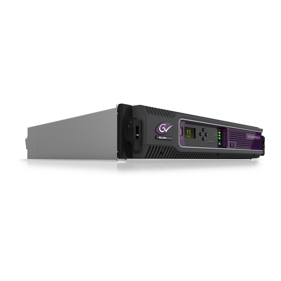
Summary of Contents for Belden Grass Valley XCU Universe XF
- Page 1 User’s Guide 3922 496 32391 October 2018 v1.4 Communication XCU UNIVERSE UXF Transmission XF FIBER Camera Power Cable On Air Power XCU Universe XF XF Transmission Base Station...
- Page 2 Liable to technical alterations in the course of further development. Trademarks Grass Valley, LDX Series and derivatives are trademarks of Belden Inc. or Grass Valley Canada. All other tradenames referenced are service marks, trademarks, or registered trademarks of their respective companies.
-
Page 3: Table Of Contents
Table of contents Chapter 1 – Introduction Welcome............11 1.1.1 About this manual . - Page 4 Chapter 4 – Operation Front panel indicators ..........33 Transmission diagnostics on the OCP .
- Page 5 Recycling Visit www.grassvalley.com for recycling information. Packing for return If a unit is being returned to Grass Valley for servicing, try to use the containers and materials of the original packaging. Attach a tag indicating the type of service required, return address, model number, full serial number and the return number which will be supplied by your Grass Valley service centre.
- Page 6 Declaration of conformity We, Grass Valley Nederland B.V., Bergschot 69, 4817 PA Breda, The Netherlands, declare under our sole responsibility that this product is in compliance with the following standards: – EN60065 Safety – EN55103-1:2009 EMC (Emission) for the following environments: (E1) Residential;...
- Page 7 Important information Read these instructions carefully and retain them for future reference. During installation and operation of this equipment, local building safety and fire protection standards must be observed. Whenever it is likely that safe operation is impaired, the apparatus must be made inoperative and secured against any unintended operation.
- Page 8 Fiber-optic transmission units CLASS 1 LASER PRODUCT LASER KLASSE 1 PRODUKT Laser safety statement (Europe) Fiber-optic transmission units are classified as a “CLASS 1 Laser Product” according to EN 60825-1, Safety of Laser products. Class 1 laser products are considered safe and do not result in biological hazard if used according to the instructions.
- Page 9 Cleaning fiber-optic connectors WARNING Never clean an optical connector attached to a fiber that is carrying light. Particles of foreign matter on the tip of a ferrule can have a disabling effect on fiber-optic transmission. Fiber-optic connectors need to be cleaned every time they are mated and unmated;...
- Page 10 Mains lead wiring for UK users The wires in the mains lead are colored in accordance with the following code: GREEN and YELLOW- EARTH BLUE- NEUTRAL BROWN- LIVE As the colors of the wires in the mains lead of this apparatus may not correspond with the colored markings identifying the terminals in your plug proceed as follows: •...
-
Page 11: Chapter 1 - Introduction
Chapter 1 - Introduction Chapter 1 Introduction 1.1 Welcome Grass Valley’s XCU Universe XF (XF Transmission Base Station) is a heavy duty, multi-standard transmission and power system designed for Grass Valley studio cameras. 1.1.1 About this manual The purpose of this manual is to present a detailed description of how to install and operate the XCU Universe XF . -
Page 12: Technology
Chapter 1 - Introduction 1.2 Technology 1.2.1 Unique Cradle concept The XF Transmission Base Station system is like no other in the world. Its unique cradle can be pre-mounted and pre-wired in a 19-inch rack, making a secure mechanical and electrical connection, permitting the XCU Universe XF box to easily slide in and out whenever needed. -
Page 13: Xf Fiber Transmission
Chapter 1 - Introduction 1.2.2 XF Fiber Transmission Grass Valley’s latest XCU Universe XF is based on full digital transmission and a proven and robust power system. The XF transmission system consists of a dockable camera adapter that fits on Grass Valley HD camera heads and an XCU Universe XF that takes care of power, signal transport and conversion and connection to the studio or OB van. -
Page 14: Main Features
Chapter 1 - Introduction 1.3 Main features • Flexible and multiple audio and video connectivity. • Unique cradle mounting concept ensures maximum flexibility at a minimum set-up time. • Many different video transmission systems are available. • Reliable video transmission of many video formats: –... -
Page 15: Chapter 2 - Installation
Chapter 2 - Installation Chapter 2 Installation 2.1 Rack installation 2.1.1 Installing rack mounting rails The XCU Cradle can be mounted in most standard 19-inch video or IT rack types. The unit needs two rack units (2 RU) of vertical space in the rack. Install two L-shaped rack mounting rails (not supplied) that match your rack type. -
Page 16: Installing The Cradle
Chapter 2 - Installation 2.1.2 Installing the cradle After mounting the rack mounting rails, install the cradle: Slide the cradle into the rack so it is supported by the L-shaped mounting rails. Fix the cradle to the front rack posts using four M6-screws (not supplied with the unit). 2.1.3 Transporting rack mounted XCUs When transporting rack mounted XCUs in a flightcase make sure to take the following precautions:... -
Page 17: Connecting Studio Cabling
Chapter 2 - Installation 2.1.4 Connecting studio cabling The studio cabling (main video outputs, control and intercom connections, studio signalling) can now be connected according to your application and studio configuration. Refer to “External video connectors” on page 56 for connectors and signals available on the cradle. More information about studio signalling, control network, intercom cabling and other studio infrastructure can be found further down this chapter. -
Page 18: Setting Up The Control Network
Chapter 2 - Installation 2.3 Setting up the control network The XCU is connected to the control network hub or router via an Ethernet cable (straight- through, not cross-over) via the C2IP (RJ45) connector. An OCP 400 (Operational Control Panel) and, if required an MCP 450 (Master Control PC), are also connected to the Ethernet network via a hub or router. -
Page 19: Setting Up Studio Signalling
Chapter 2 - Installation 2.5 Setting up studio signalling Connect the studio signalling system to the rear of the XCU. The wiring of the signalling connector is shown below: Prev.out send Signal Send pin Return pin Prev.out ret. Call out send Call out return ISO in send ISO in return... -
Page 20: Dry Contact With Multiple Xcus
Chapter 2 - Installation Menu setting Input is shorted: Input is open: LH (low-high) Function is Active Function is Inactive HL (high-low) Function is Inactive Function is Active 2.5.2 Dry contact with multiple XCUs This is an example of an On Air signalling with multiple XCUs using a common contact. On-Air (Tally) 1 On-Air in ext. -
Page 21: Common Ground
Chapter 2 - Installation 2.5.3 Common ground On-Air (Tally) 1 On-Air in ext. (pin 4) Signalling connector On-Air in ext. return (pin 12) Base Station 1 On-Air (Tally) 2 On-Air in ext. (pin 4) Signalling connector On-Air in ext. return (pin 12) Base Station 2 On-Air (Tally) n On-Air in ext. -
Page 22: Voltage Level
Chapter 2 - Installation 2.5.4 Voltage level ISO 1a 0 .. 2.5 V ISO in ext. send (pin 3) ISO 1b 4 .. 24 V ISO in ext. return (pin 11) On-Air (Tally) 1a 0 .. 2.5 V On-Air in ext. send (pin 4) On-Air (Tally) 1b 4 .. -
Page 23: Open Circuit/Voltage Level
Chapter 2 - Installation 2.5.5 Open circuit/Voltage level ISO 1a ISO in ext. send (pin 3) Open/ 4..24 V ISO 1b ISO in ext. return (pin 11) On-Air (Tally) 1a On-Air in ext. send (pin 4) Open/ 4..24 V On-Air (Tally) 1b On-Air in ext. -
Page 24: Setting Up External Audio Level
Chapter 2 - Installation 2.6 Setting up external audio level The camera audio levels for channel 1 and 2 can be externally controlled by the XCU Universe XF. In the camera system menu, go to the INSTALL > AUDIO > AUDIO GAIN MODE item and select Ext. -
Page 25: Chapter 3 - Configuration
Chapter 3 - Configuration Chapter 3 Configuration 3.1 Front navigation panel The front navigation panel is used to display and set the camera number, to display operational and diagnostic information and to access and navigate the internal XCU menu. Graphic display Back Communication Transmission... -
Page 26: Accessing The Xcu Menu
Chapter 3 - Configuration • Use the Up [3] and Down [4] buttons to select the camera number. Push the Forward button to confirm the settings or push the Back button to cancel the selection. Camera number Cancel 3.3 Accessing the XCU menu 3.3.1 Using the XCU front navigation panel The easiest way to navigate the XCU menu is by using the front navigation panel. -
Page 27: Navigating The Menu
Chapter 3 - Configuration • Push the Selection button to choose the BS menu. EXIT TOGGLE EXIT TOGGLE EXIT TOGGLE Diag Menu DOWN SELECT PREV NEXT PREV NEXT PREV NEXT • Push the Selection button enter the menu. • The menu appears on the Monitoring output of the XCU. Use the appropriate selection buttons to navigate the menu. -
Page 28: Leaving The Menu
Chapter 3 - Configuration When you first enter a menu (other than the main menu) the cursor is positioned next to the first item. The TOP and PREVIOUS entries are not immediately visible but are located above the first item. Use the control to scroll up to them. •... -
Page 29: User Levels
Chapter 3 - Configuration If the value is unavailable it cannot be changed. This is indicated by three dashes (---). This can occur, for example, when a function is switched off. The analog values associated with that function are then unavailable. If there are only two values associated with the function, then pressing the Select button toggles between these two values. -
Page 30: Intercom Setup
Chapter 3 - Configuration 3.5 Intercom setup The studio camera systems offer extensive intercom facilities between cameraman, tracker (floor man), XCU and studio. To help you set up and operate the intercom system, the following controls are available: • XCU menu system •... -
Page 31: Color Bars
Chapter 3 - Configuration 3.6 Color bars For set up and test purposes, the XCU can generate a color bar signal at the HD-SDI output connectors. This signal will be only present when no camera is connected and no valid video signal is received. - Page 32 Chapter 3 - Configuration XCU Universe XF XF Transmission Base Station User’s Guide (v1.4)
-
Page 33: Chapter 4 - Operation
Chapter 4 - Operation Chapter 4 Operation 4.1 Front panel indicators During setup and operation operation and transmission can be monitored on the XCU front panel. A graphical display and several LED indicators provide information about important operational and diagnostic functions. Communication Transmission Camera Power... - Page 34 Chapter 4 - Operation Communication indicator This green indicator lights when communication between camera and the XCU is established and working correctly. A red light indicates a communication error. Transmission indicator This indicator lights when a working signal transmission is established between the camera and XCU.
-
Page 35: Transmission Diagnostics On The Ocp
Chapter 4 - Operation 4.2 Transmission diagnostics on the OCP With an Operational Control Panel (OCP 400) is connected to the system, transmission can be monitored in the diagnostics page of the panel: Cable quality from XCU to camera EXIT TOGGLE Signal quality from XCU to FibA Cable... - Page 36 Chapter 4 - Operation Insert small flat Insert small flat screwdriver here screwdriver here to open clip to open clip Insert a very small screwdriver into the hole at the left side and then at the right side of the fuseholder to unclip both side of the fuseholder. Extract the fuseholder from the mains entry by pulling of the small clip at the bottom of the fuseholder.
-
Page 37: Chapter 5 - Xcu Menu Reference
Chapter 5 - XCU menu reference Chapter 5 XCU menu reference 5.1 Video menu Menu item Settings Default Level Description Colour Bar Colour Bar Off, On User 1 Turns color bar on or off (when camera signal is not present) Bar Type Split, Full Split... -
Page 38: Monitoring Menu
Chapter 5 - XCU menu reference Menu item Settings Default Level Description Level Dependence 0..99 User 1 Sets the 4K Detail reduction level for shadow areas. Soft Detail Off, On User 1 Switches 4K Soft Detail on or off. This function reduces the amount of detail added fo large transitions. -
Page 39: Audio/Intercom Menu
Chapter 5 - XCU menu reference 5.3 Audio/Intercom menu Menu item Settings Default Level Description Audio Audio 1 Level 0dB, 6dB User 1 Selects studio attenuation level for Audio input 1 Audio 2 Level 0dB, 6dB User 1 Selects studio attenuation level for Audio input 2. Intercom Source Analog, IP... -
Page 40: Install Menu
Chapter 5 - XCU menu reference 5.4 Install menu Menu item Settings Default Level Description Camera ConnectType Cable, Network Cable User 2 Selecsts theconnection type between camera and XCU: Cable = camera and XCU are connected directly by the transmission cable. Network = camera and XCU are connected via the IP Media Network (only available when XF Transmission IP Tunneling... - Page 41 Chapter 5 - XCU menu reference Menu item Settings Default Level Description Onair R Inp. Low/High, High/ Low/High User 0 Selects switch mode for the Red On Air signalling Low, Open/High, input. High/Open Onair Y Inp. Low/High, High/ Low/High User 0 Selects switch mode for the Yellow On Air (ISO) Low, Open/High, signalling input.
- Page 42 Chapter 5 - XCU menu reference Menu item Settings Default Level Description IP digit 1 1..250 User 0 IP digit 2 0..255 User 0 Selects Nameserver 2 IP address. IP digit 3 0..255 User 0 IP digit 4 1..254 User 0 Apply settings Exec, ..
-
Page 43: Security Menu
Chapter 5 - XCU menu reference Menu item Settings Default Level Description SDI Live Mode Combined, Combined User 3 In high-speed video modes this selects the method 1 Phase, of combining high-speed phases for the live viewing (2 Phases, 3 output (Live/Effect (D) connectors): Phases) Combined: all phases (3 or 6) are combined to obtain... - Page 44 Chapter 5 - XCU menu reference Menu item Settings Default Level Description Connector None, Fiber, Triax, None User 2 <Advanced settings> Error Status Unknown, Open, Unknown User 2 <Advanced settings> Power Off, Overload, Short, Cam Off, Cam On, Error Int.Error Unknown, VMtest, Unknown User 2...
- Page 45 Chapter 5 - XCU menu reference Menu item Settings Default Level Description Signal Status OK, Critic, Error, NoSig User 0 <Advanced settings> NoSig, Unknown RX Margin — — User 0 <Advanced settings> CRC Error Count 0..65535 Service <Advanced settings> Fib B (XCU->CAM) Cable Status OK, Critic, Error, NoSig...
- Page 46 Chapter 5 - XCU menu reference Menu item Settings Default Level Description CRC Error 0..65535 Service <Advanced settings> Count -> CAM RX Margin — — Service <Advanced settings> CRC Error 0..65535 Service <Advanced settings> Count <- CAM RX Margin — —...
- Page 47 Chapter 5 - XCU menu reference Menu item Settings Default Level Description Video inputs Extern 1 Carrier Yes, No User 1 <Advanced settings> Locked Yes, No User 1 <Advanced settings> VideoMode Unknown, SD, Unknown User 1 <Advanced settings> 1080i59, 1080i50, 720p59, 720p50, 1080p59, 1080p50, 1080i47...
-
Page 48: Service Menu
Chapter 5 - XCU menu reference Menu item Settings Default Level Description Version 0..65535 User 2 <Advanced settings> PCB Info Board GEB, UIB, COB, User 2 <Advanced settings> IDB, TRB, PDB, — — User 2 <Advanced settings> 12NC 0..65535 User 2 <Advanced settings>... - Page 49 Chapter 5 - XCU menu reference Menu item Settings Default Level Description Format Off, Running Service <Advanced settings> Lic. Partition Status Unknown, Busy..., Unknown Service <Advanced settings> OK, Error, NonGV, Init... USB available No, Yes Service <Advanced settings> XCU Universe XF XF Transmission Base Station User’s Guide (v1.4)
- Page 50 Chapter 5 - XCU menu reference XCU Universe XF XF Transmission Base Station User’s Guide (v1.4)
-
Page 51: Chapter 6 - Connectors And Signals
Chapter 6 - Connectors and signals Chapter 6 Connectors and signals 6.1 Connector overview Ext 1 in Ext 2 in —A— HD-SDI TP in Ref in Ref out Ext 1 out Ext 3 in —B— TP out C2IP —D— —C— CVBS --SDI Out-- Ethernet... -
Page 52: Main Video (For Hd (1080I/720P) Video Modes)
Chapter 6 - Connectors and signals 6.1.3 Main video ( for HD (1080i/720p) video modes) --A-- Ext 1 in Ext 2 in TP in Ref in HD-SDI Ref out --B-- Ext 1 out Ext 3 in TP out --D-- --C-- CVBS CV V B --SDI Out--... -
Page 53: Main Video (For 3G (1080P) Video Modes)
Chapter 6 - Connectors and signals 6.1.4 Main video (for 3G (1080p) video modes) --A-- Ext 1 in Ext 2 in TP in Ref in HD-SDI Ref out --B-- Ext 1 out Ext 3 in TP out --D-- --C-- CVBS CV V B --SDI Out-- Live-Effect... -
Page 54: Main Video (For 4K Video Modes)
Chapter 6 - Connectors and signals 6.1.5 Main video (for 4K video modes) --A-- Ext 1 in Ext 2 in TP in Ref in HD-SDI Ref out --B-- Ext 1 out Ext 3 in TP out --D-- --C-- CVBS CV V B --SDI Out-- Live-Effect HD Video out... -
Page 55: Main Video (For Hs And Xs Video Modes)
Chapter 6 - Connectors and signals 6.1.6 Main video (for HS and XS video modes) --A-- Ext 1 in Ext 2 in TP in Ref in HD-SDI Ref out --B-- Ext 1 out Ext 3 in TP out --D-- --C-- CVBS CV V B --SDI Out--... -
Page 56: External Video Connectors
Chapter 6 - Connectors and signals 6.1.7 External video connectors --A-- Ext 1 in Ext 2 in TP in Ref in HD-SDI Ref out --B-- Ext 1 out Ext 3 in TP out --D-- --C-- CVBS --SDI Out-- Live-Effect HD Video out Connector Signal Ext 1-in... -
Page 57: Signalling Connector
Chapter 6 - Connectors and signals Area 2: Reference connectors Connector Signal Ref in Reference input signal (HD Tri-Level sync or SD Black Burst are accepted) Ref out Reference loop-through output signal *) *) This output signal is always looped-through even when the XCU is not mounted in its cradle. ☞... -
Page 58: Intercom Connector
Chapter 6 - Connectors and signals 6.1.10 Intercom connector Pin Description Pin Description Prod out (4-wire out, 2-wire Prod out return (4-wire out, 2- in/out) wire in/out) Prod in (4-wire only) Prod in return (4-wire only) SubD 15-pin female connector Prod in shield (4-wire only) Eng in shield (4-wire only) Eng in (4-wire only) -
Page 59: Ip Trunk Connector (Bottom)
Chapter 6 - Connectors and signals 6.1.13 IP Trunk connector (bottom) Ethernet 10Base-T, 100Base-TX, Pin Description 1000BASE-T and Gigabit Ethernet compatible. Transmit data + (TX+ ) Transmit data - (TX-) Receive data+ (RX+) 8-pin standard TD2+ RJ-45 ethernet connector TD2- Receive data - (RX-) TD3+ TD3-... -
Page 60: Analog Audio Out 2 Connector
Chapter 6 - Connectors and signals 6.1.17 Analog Audio OUT 2 connector Sensitivity range: -64 dBu to -22 dBu Pin Description Signal at pin 2 of audio output is in Audio shield phase with signal at pin 2 of audio input. -
Page 61: Chapter 7 - Specifications
Chapter 7 - Specifications Chapter 7 Specifications 7.1 Technical specifications Item Value General Dimensions (W x H x D) 438 x 88 x 440 mm (17.2 x 3.5 x 17.3 in) excluding transmission connector Weight (max.) 7.3 kg (16.1 lbs) excl. cradle; 11.8 kg (26.0 lbs) incl. cradle Operating temperatures 0 to +45 °C (+32 to +113 °F) Storage temperatures... - Page 62 Chapter 7 - Specifications Item Value 3x BNC, 0.8 Vpp, 75 , HD-SDI or SDI + 1x loop through output External video inputs Data connectors C2IP camera control Standard Ethernet RJ-45 connector, 100 Mb Ethernet Standard Ethernet RJ-45 connector, 1 Gb/100Mb for Ethernet Trunk between Base Station and camera.
-
Page 63: Dimensions
Chapter 7 - Specifications 7.2 Dimensions 482 mm 438 mm Communication Transmission Camera Power Cable On Air Power XF Fiber XCU Universe XF XF Transmission Base Station User’s Guide (v1.4) - Page 64 Chapter 7 - Specifications XCU Universe XF XF Transmission Base Station User’s Guide (v1.4)
- Page 65 XCU Universe XF XF Transmission Base Station User’s Guide (v1.4)
- Page 66 Copyright Grass Valley Nederland B.V.
Need help?
Do you have a question about the Grass Valley XCU Universe XF and is the answer not in the manual?
Questions and answers