
Summary of Contents for Vemm Tec PTZ-BOX 5.0
- Page 1 GAS-VOLUME CONVERSION DEVICE PTZ-BOX 5.0 Manual Specifications Technical description Mounting instructions Configuration Single-channel gas conversion device Approved for installation in potentially explosive atmospheres 09-2019...
- Page 2 PTZ-BOX 5.0 User manual, document edition: 13 Safety measures This measurement device can be operated only by an operator trained in compliance with the technical terms, safety regulations, and standards. It is necessary to consider any other legal and safety regulations stipulated for special applications. Similar measures also apply for special applications.
- Page 3 PTZ-BOX 5.0 User manual, document edition: 13 • do not dispose of the product with other unsorted waste, • do not burn the product. By adhering obligations of waste electrical and electronic equipment controlled disposal mentioned above, you avoid harmful effects on the environment and human health.
-
Page 4: Table Of Contents
PTZ-BOX 5.0 User manual, document edition: 13 Table of contents Introduction ............................. 7 Device description ........................7 Function principle ........................8 1.2.1 General characteristics ....................8 1.2.2 Measurement – calculation cycles .................. 8 1.2.3 Emergency state ......................8 1.2.4 Calculation of conversion factor C ................... 9 1.2.5... - Page 5 PTZ-BOX 5.0 User manual, document edition: 13 Pressure measurement ......................24 Compressibility calculation ....................25 5.3.1 Ranges of using gas composition parameters ............... 26 Inputs and outputs ........................28 Inputs ............................. 28 6.1.1 Counting inputs: LF, HF, EN, SCR ................... 28 6.1.2...
- Page 6 PTZ-BOX 5.0 User manual, document edition: 13 Device start up ..........................41 Operation ..........................42 Keyboard ..........................42 Signaling of operating state ....................43 Main menu functions ......................44 Menu structure ........................45 10.4.1 Main menu ........................46 10.4.2 Measured values ......................47 10.4.3...
-
Page 7: Introduction
Introduction Device description Gas volume conversion device PTZ-BOX 5.0 is a device used for measurements of gas volume at base conditions and energy. It is designed to be used at gas measuring stations and pressure reduction- measuring stations. It can cooperate with rotor and turbine gas meters. -
Page 8: Function Principle
• PTZ-BOX 5.0 is a device powered by internal battery, but it also can be powered by external power supply. In standard version, at typical operating conditions (1-2 readouts per month) 1 piece of battery allows up to five years of lifetime. -
Page 9: Calculation Of Conversion Factor C
During emergency state, the main counters Vb, E and M are stopped. Vm counter is always active. Emergency state of PTZ-BOX 5.0 is active as long as an alarm from a system group is active. 1.2.4 Calculation of conversion factor C... -
Page 10: Increment Of Volume At Measurement Conditions
PTZ-BOX 5.0 User manual, document edition: 13 �� ��1 = (1b) ���� Figure 1. Diagram of calculation algorithm operation WARNING! In algorithms SGERG-88, AGA8-G1, AGA8-G2, AGA NX-19-mod and K1-const device requires to program values of superior calorific value Hs and relative density d specified for used base conditions Tb and pb and combustion process T1 and P1 (always P1=pb). -
Page 11: Averaged Conversion Factor
PTZ-BOX 5.0 User manual, document edition: 13 LF factor – LF input pulse rate. In configurations with HF as main counting input (configurations: HF1, HF1/LF1, HF1/HF2, HF1/SCR, HF1/EN) increment of volume at measurement conditions dVm is calculated with formula: ������... -
Page 12: Increment Of Mass
PTZ-BOX 5.0 User manual, document edition: 13 Hs – superior calorific value. Increments dE are summed up to E counter during normal operation and to Ee during emergency mode. 1.2.9 Increment of mass ������ × ������ = ���� where: dVb – increment of volume at base conditions, rob –... -
Page 13: Flow Of Energy
Correction is also used to calculate volume, energy and mass, parameters after correction are: Vc, Vb, E, M. Dimensions Figure presents basic dimensions of PTZ-BOX 5.0 housing. During mounting, note that enough space must be left in order to enable subsequent dismantling for maintenance or repair. - Page 14 PTZ-BOX 5.0 User manual, document edition: 13 Figure 2. Dimensions and mounting holes locations of PTZ-BOX 5.0 housing: A – pressure sensor, B – mounting hole...
-
Page 15: Technical Description
PTZ-BOX 5.0 User manual, document edition: 13 Technical description Device construction Device consists of two boards: Main board in bottom part of the casing, containing processor, input/output connectors (including pulse inputs, temperature sensor input, signaling inputs, digital outputs, communication ports, power supply terminal), terminal for internal pressure sensor, batteries (main and backup), sim tray for optional modem. -
Page 16: Power Supply
PTZ-BOX 5.0 User manual, document edition: 13 1, 2 - input of external power supply, 3, 4 - input of external power supply for transmission ports, 5..8 - transmission ports COM1 and COM2, 9..10 - power output for external reserve transducers, 11..14... - Page 17 PTZ-BOX 5.0 User manual, document edition: 13 PTZ-BOX 5.0 is the intrinsically safe equipment. The housing of the device should be sealed – replacement of the battery can only be carried out by an authorized person, i.e. a factory or authorized service representative or other persons authorized by the manufacturer.
-
Page 18: Backup Battery
Sealing of the unit PTZ-BOX 5.0 as a device for billing, should be protected against unauthorized access. To do this, unit housing is secured with seals like presented on figure below and access to the menu is protected by a password system. - Page 19 I – installer seal, V – temporary seal (for the time of transport). Figure 5. External sealing of PTZ-BOX 5.0 device After mounting of device, installation staff is obligated to place own wire protection seal accordingly to scheme on Figure 5. During transportation, terminals chamber is protected with temporary seal –...
- Page 20 PTZ-BOX 5.0 User manual, document edition: 13 M – MID sealing mark, I – installer seal, N – seal according to national regulations, Figure 6. Internal sealing of PTZ-BOX 5.0. Figure 7. Example of MID sealing mark void sticker...
-
Page 21: Nameplates
Safety General The PTZ-BOX 5.0 is intrinsically-safe device. It should be used in accordance with the requirements of this documentation and the conditions specified in the ATEX certificate. The manufacturer's declaration of the IP66 housing tightness class will be valid only if... - Page 22 The PTZ-BOX 5.0 compliant with MID, on the name plate, next to the “CE” sign has the supplementary metrology marking consists of: capital letter “M” followed by last two digits of the year of its affixing, surrounded by a rectangle.
-
Page 23: Ex Marking
PTZ-BOX 5.0 User manual, document edition: 13 Ex marking Device is approved for use in potentially explosive atmospheres. Marking: II 1G Ex ia IIB T4 Ga Certificate FTZU 17 ATEX 0165X Operating environment: Device is approved to use at the 0, 1 and 2 zones threatened with explosion of mixture of: vapors, gases and explosive vapors with air which are placed in IIB or IIA explosive group and temperature class T1, T2, T3, T4. -
Page 24: Metrological Properties
Metrological properties Temperature measurement The temperature sensor CT6A (Optional: Pt1000/2w or Pt1000/4w/cl.A) is part of each PTZ-BOX 5.0 device. The sensor is available in 2 types of sheath length: fixed length “50” and adjustable length “140,160,180”. Each piece of sensor is checked at the manufacturer’s laboratory to meet the accuracy class requirements. -
Page 25: Compressibility Calculation
Compressibility calculation In PTZ-BOX 5.0 there is possibility to choose computation algorithm of compressibility factor: Value ConfAlgZ Name of algorithm AGA8-92DC (full gas composition) SGERG-88 (Hs-d-XCO2-XH2 or full gas comp.) -
Page 26: Ranges Of Using Gas Composition Parameters
PTZ-BOX 5.0 User manual, document edition: 13 Despite fact, that algorithms AGA8-G2 and AGA NX-19mod are not using calorific value Hs for calculation of compressibility factor, it must be programmed, because it is necessary for correct computing of energy counter. - Page 27 PTZ-BOX 5.0 User manual, document edition: 13 protocols. In case of remote modification, default permissible deviation from 100% of components sum is 0.001%. Gas parameter must be in following ranges (SGERG-88, AGA8-G1, AGA8-G2, AGA NX-19mod, K1=const): Algorithm Parameter SGERG-88 AGA8-G1...
-
Page 28: Inputs And Outputs
PTZ-BOX 5.0 User manual, document edition: 13 Inputs and outputs Inputs A total of 8 digital inputs, marked as DI1 to DI8 can be connected to the device: 6 configurable potential-free contact inputs (DI1 to DI5 and DI8): o Measuring inputs LF1, LF2 (inputs DI3, DI4) – frequency up to 60 Hz with the... -
Page 29: Configuration Of Counting Input Encoder (En, Scr)
PTZ-BOX 5.0 User manual, document edition: 13 • HF1/LF1 (63) – Vm and main counters are driven from HF1 input, control counter V2 driven from LF1 input, • HF1/HF2 (67) – Vm and main counters are driven from HF1 input, control counter V2 driven from HF2 input, •... -
Page 30: Reverse Flow Support
0. 6.1.4 Digital inputs PTZ-BOX 5.0 is equipped with up to 8 binary inputs, which may – according to chosen configuration of counting inputs – work as digital (signaling) inputs. These inputs are intrinsically safe. Inputs DI1..DI5 and DI8 are adapted to work with potential-free reed contacts. -
Page 31: Outputs
Outputs PTZ-BOX 5.0 is equipped with four controlling outputs of „open collector” type, which allow cooperation with external systems of automation and signaling. Outputs are made in intrinsically safe version, so it’s required to use Ex barriers when connecting external non-intrinsically safe devices. -
Page 32: Time Synchronized Output
PTZ-BOX 5.0 User manual, document edition: 13 Range of frequency is 1÷1000 Hz. Configuration of minimum and maximum frequency is performed on parameters FOMin and FOMax accordingly. Scaling of selected controlling parameter (to match values of this parameter with min and max frequency) is performed on parameters DO1FMin and DO1FMax. -
Page 33: Communication With The Ptz-Box 5.0
Communication with the PTZ-BOX 5.0 Serial ports PTZ-BOX 5.0 is equipped with two channels of serial transmission: COM1 and COM2 in standard RS- 485 and wireless transmission port COM3 in standard IEC 62056-21 (OPTO). All of transmission ports are working independently and allow to transmit with speed given below. -
Page 34: Transmission Protocols
• ModBUS – RTU and TCP (modem only). Device recognizes transmission protocol automatically. Transmission protocols implemented in PTZ-BOX 5.0 differ from each other by functionality of remote readout and parameters modification. 7.4.1 Restrictions of remote data access Device’s software allows to restrict remote access to measurement data when using all available transmission protocols. -
Page 35: Types Of Transmitted Data - Gazmodem
GazModem protocol allows to: readout of current measurement data, readout of registered data, readout of events and alarms, time synchronization, modification of parameters values. All data structures are described in document “PTZ-BOX 5.0 User data structure”. 7.4.3 Types of transmitted data – ModBUS ModBUS protocol allows to readout of current data and modifications of parameters. -
Page 36: Functions
PTZ-BOX 5.0 User manual, document edition: 13 Functions Entering data into the device Configuration data can be entered into the PTZ-BOX 5.0 using device keyboard or by remote transmission. Remote configuration through digital communication channels (serial ports COM1, COM2, optical, NFC and modem) can be performed with PTZcom software available from manufacturer’s website:... - Page 37 2 and 3. This setting is performed on parameter CustAccess. Setting it to value 1 will allow such modifications, 0 – blocks it. All of device’s parameters designed for configuration are described in document “PTZ-BOX 5.0 User data structure”, where are also indications what kind of privileges are required to do modification.
-
Page 38: Clock
PTZ-BOX 5.0 User manual, document edition: 13 Default settings give following privileges for specific group of users: • METROLOGIST o privileges for data readout o privileges for configuration of all device’s parameters (including calibration of legally relevant measuring inputs of pressure and temperature) •... -
Page 39: Archives
, last gas day of month. Storage period of periodic data 2 is up to about 800 records; Description of archival data sets registered with fixed period is available in document “PTZ-BOX 5.0 User data structure”. 8.4.3 Change of registered data set Device’s software allows to change sets of both registered data types independently. -
Page 40: Momentary Registration
They do not stop main counters and don’t change status of registered and measured data. Exception are events Device Startup and Time changed, which are changing state of measured and registered data to discontinuity. In PTZ-BOX 5.0 there are 3 types of memory of events and alarms: • Alarms memory (i.e. AlarmLOG);... -
Page 41: Software Update
ConfTrig). Software update PTZ-BOX 5.0 is equipped with function for program updating. Software update may be locked for user (based on national law). Function of this lock is placed on parameter LockFW1. Value of 1 turns on the lock. -
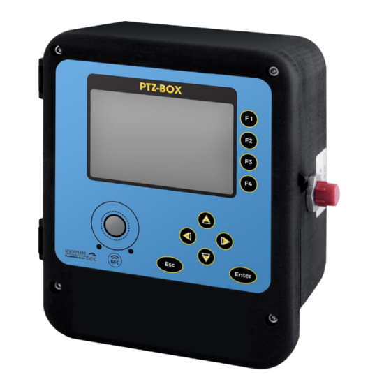
Page 42: Operation
PTZ-BOX 5.0 User manual, document edition: 13 Operation Keyboard Local communication between user and device is realized by keyboard and graphic display. Keyboard is equipped with two function keys Enter, Esc, four arrow keys and four shortcut keys F1÷F4. F1÷F4 keys are shortcut... -
Page 43: Signaling Of Operating State
PTZ-BOX 5.0 User manual, document edition: 13 When viewing values of parameters, it is possible to go quickly to searched parameter. To do so, it is necessary to know index of searched parameter. While browsing current Cursor displays a parameters of the device,... -
Page 44: Main Menu Functions
PTZ-BOX 5.0 User manual, document edition: 13 User logged locally (in this example – level 4 of privileges) Active alarms or events, pulsation – new alarms /events Active events, pulsation – new events No active alarms, pulsation – there were unchecked alarms/events that have ended Modem signal reception strength (in this example –... -
Page 45: Menu Structure
PTZ-BOX 5.0 User manual, document edition: 13 When viewing parameters, use the cursors to select the parameter to modify Press Enter to select currently highlighted parameter and enter edit mode In the edit mode of parameter value, the cursors will let... -
Page 46: Main Menu
PTZ-BOX 5.0 User manual, document edition: 13 10.4.1 Main menu Main menu structure. Expanded sub-menus are presented below. -
Page 47: Measured Values
PTZ-BOX 5.0 User manual, document edition: 13 10.4.2 Measured values This menu allows to view current and archive values of main parameters – including measured parameters from sensors and counters. It also allows to configure settings determining registration timing. - Page 48 PTZ-BOX 5.0 User manual, document edition: 13 10.4.2.1 Archive This sub-menu allows to view all types of registered data: periodic, hourly, daily, monthly, momentary and periodic 2. For selected set of parameters – minimal, maximal and average values for three different time periods. It also allows access to alarms registered in the device.
-
Page 49: Calculation Settings
PTZ-BOX 5.0 User manual, document edition: 13 10.4.3 Calculation settings This menu consists of parameters needed for calculation of conversion factor – gas composition, base conditions, selection of algorithm for calculations. It also contains parameters determining time of data registration. -
Page 50: Device Settings
PTZ-BOX 5.0 User manual, document edition: 13 10.4.4 Device settings This menu consists of following sub-menus: Name plate – displays basic information about the device, Inputs – allows to configure all available inputs: sensors (p1, t, p2), pulse (LF, HF), settings for gas meter and digital inputs, Digital outputs –... - Page 51 PTZ-BOX 5.0 User manual, document edition: 13 10.4.4.1 Device settings – Inputs This menu allows to view and configure settings for available sensors, pulse and digital inputs.
- Page 52 PTZ-BOX 5.0 User manual, document edition: 13 10.4.4.2 Device settings – Digital outputs This menu allows to view and configure settings for digital outputs. 10.4.4.3 Device settings – Communication This menu allows to view and configure parameters of serial ports and modem.
-
Page 53: Alarms
PTZ-BOX 5.0 User manual, document edition: 13 10.4.5 Alarms This menu allows to access list of currently active and archived alarms. 10.4.6 All parameters This menu lists all parameters available in the device. 10.4.7 User menu This menu lists parameters defined by user. These parameters are available in both “live” and “frozen”... -
Page 54: Installation
Installation Mechanical installation PTZ-BOX 5.0 can be mounted on a wall or gas pipeline. After installation, pulse tube should be connected with gas pressure sensor which has metric thread M12 x 1.5. Pulse tube should be equipped with three-way valve that allows cutting off the gas supply to the sensor or connection of an additional calibration device. - Page 55 PTZ-BOX 5.0 User manual, document edition: 13 Figure 11. Mounting dimensions...
-
Page 56: Preparation Of The Wires
PTZ-BOX 5.0 User manual, document edition: 13 Preparation of the wires Wires must be prepared according to instruction presented below. Shielding of the power supply wire should be insulated at the device point and grounded at the power supply point. -
Page 57: Recommended Wires
PTZ-BOX 5.0 User manual, document edition: 13 Recommended wires Measurement inputs: LF, HF, encoder, tamper switch, digital input type NAMUR. Wires: • LIYCY or LIYY 2 x 0.25 - 0.5 mm • LIYCY or LIYY 4 x 0.25 - 0.5 mm Maximum length 10 m Intrinsically safe digital input. -
Page 58: Connection Of The Wires
PTZ-BOX 5.0. If gas meter is not equipped with tamper switch – it’s input on unit terminal strip must be short-circuited. -
Page 59: Specifications
PTZ-BOX 5.0 User manual, document edition: 13 Specifications Dimensions 197 x 181 x 82 mm Weight about 1.5 kg Housing material Polycarbonate -25 °C +70 °C, batteries Saft LS33600, Tadiran SL2780 Ambient temperature range -25 °C +50 °C, batteries EVE 34165 Max 95%. - Page 60 PTZ-BOX 5.0 User manual, document edition: 13 • Source of power supply with 5.7 V nominal output voltage External supply (max. 6.51 V, 3.5 W) • COM1 - standard RS-485, active with external power supply, • COM2 - standard RS-485, galvanic insulated, typically active...
- Page 61 PTZ-BOX 5.0 User manual, document edition: 13 The maximum permissible 0.5 % at reference conditions error (MPE) according to 1 % at nominal operating conditions standard „EN 12405-1” Gas pressure p1 ≤ 120 bar Gas temperature t in range: -10,15°C ÷ 64,85°C Gas pressure p1 ≤...
-
Page 62: Intrinsically Safe Parameters
PTZ-BOX 5.0 User manual, document edition: 13 Intrinsically safe parameters External power supply (POWER SUPPLY) - Terminals 2 (V ) to 1 (GND): = 6.51 V; P = 3.5 W; I = 1.1 A; L = 0; C = 12 µF External power supply of communication ports (COM SUPPLY) –... - Page 63 PTZ-BOX 5.0 User manual, document edition: 13 Gas group IIA: L = 800 mH; C = 100 µF Gas group IIB: L = 400 mH; C = 13 µF Sensor Pt1000 – Terminals 32 (I+), 31 (I-), 34 (U+), 33 (U-) to GND = 6.51 V;...
-
Page 64: Configuration
PTZ-BOX 5.0 User manual, document edition: 13 Configuration After device installation and connection according to manual, it is necessary to configure device measurement system parameters. In order to ensure correct operation it’s recommended to program following parameters: • Pulse LF and HF weight – Setting of pulse weight must be compatible with description on name plate of gas meter. -
Page 65: Manufacturer Data
PTZ-BOX 5.0 User manual, document edition: 13 Manufacturer data vemm tec Messtechnik GmbH Gartenstrasse 20 14482 Potsdam, Germany info@vemmtec.com www.vemmtec.de 098-102-001 Changes in course of technical development are reserved. 09-2019.
Need help?
Do you have a question about the PTZ-BOX 5.0 and is the answer not in the manual?
Questions and answers