Advertisement
Quick Links
User Manual
User Manual
Laser Distance Sensor
Laser Distance Sensor
OWLF series
Welotec GmbH
Zum Hagenbach 7 D-48366 Laer
www.welotec.com info@welotec.com
Fon: +49 (0)2554/9130-00 Fax: +49 (0)2554/9130-10
1
Safety instruction
Laser safety
• The laser diode installed in the OWLF emits visible red laser lights. This
laser belongs to the Class 2 laser standard specified by the IEC 60825-1
/ 2001. It also complies with 21 CFR 1040.10 and 1040.11 except for
deviation pursuant to laser notice No. 50, July 2001.
• Max. average output power < 1 mW
• Laser radiation, do not stare into beam
• To avoid uncontrolled laser exposure we recommended stopping the
beam with a matte object.
• For laser safety reasons, the voltage supply of the sensors must
be turned off when the whole system or the machine is turned off.
• Safety concept information and limiting parameters as published in
the sales documentation apply at all times.
Seite / Page 3
Contents
. 1
S
a
e f
y t
n i
t s
u r
t c
o i
. 2
I
t n
o r
d
u
t c
o i
n
. 3
F
u
n
t c
o i
n
l a
r p
n i
. 4
M
o
u
t n
n i
g
n i
t s
u r
. 5
A
p
l p
c i
t a
o i
n
h
n i
. 6
T
e
a
c
h
n i
g
h t
e OWLF
. 7
l A
r a
m
o
u
p t
t u
. 8
S
y
n
c
h
o r
n
z i
t a
o i
. 9
T
e
c
h
n
c i
l a
d
a
a t
10. Connection diagram and pin assignment
1
. 1
G
o r
u
n
d
n i
g
c
o
n
1
. 2
S
e
v r
c i
e
n
o
e t
s
1
. 3
A
c
c
e
s
s
r o
e i
s
1
. 4
T
o r
u
b
e l
s
h
o
t o
n i
2
Introduction
The latest generation of laser distance sensors are setting new standards in terms of speed and
performance. The short response time (300...900µs) makes it possible to measure small and fast
moving objects up to 600 mm away and 0.3...2.7ms up to 1000 mm away. The advanced teach-in
function allows arbitrarily configuring the measuring range between the default limits in order to
increase the resolution. This allows the complete output swing of 4 – 20 mA and 0 – 10 V to be
mapped on the new range.
The alarm output switches on as soon as the sensor receives no usable signal or as soon as the
object is outside the measuring range.
The sync. output allows the sensor to synchronize the measurement or to use several sensors in a
non-synchronous mode when they would normally interfere optically or to synchronize sensors to a
machine clock or pulse.
The distance measurement is based on the triangulation principal. The use of a photodiode array as
the receiver and the intelligence of a high performance microcontroller produce measuring results
that are almost independent of object colors and just a very small linearity error in the analog output
signal.
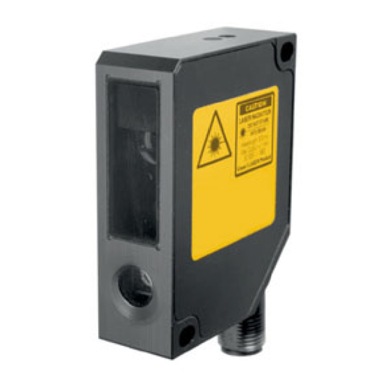
The rugged sensor has a metal housing with a front cover made of glass. The 90° rotating connecter
allows wiring the sensor from the bottom or the rear .
n
s
c
p i
e l
t c
o i
n
s
s t
n
n i
p
t u
c
e
t p
g
Seite / Page 2
Seite / Page 4
3
4
5
6
1
1
1
5
3
2
3
3
3
7
40
4
1
4
2
4
3
4
4
Advertisement

Subscribe to Our Youtube Channel
Related Manuals for Welotec OWLF Series

Summary of Contents for Welotec OWLF Series
- Page 1 Contents User Manual User Manual e OWLF Laser Distance Sensor Laser Distance Sensor OWLF series 10. Connection diagram and pin assignment Welotec GmbH Zum Hagenbach 7 D-48366 Laer www.welotec.com info@welotec.com Fon: +49 (0)2554/9130-00 Fax: +49 (0)2554/9130-10 Seite / Page 2...
- Page 2 Functional principle Mounting instructions • For a proper mounting, the mounting surface has to be flat. Be aware of the max. tightening The distance measured is based on the triangulation principle. The emitted laser beam falls on the object as a small light spot and will be reflected diffusely. The position of the received light spot on torque.
- Page 3 Profile measurement: Several sensors without mutual optical interferences: For profile measurements, the sensor axes should be perpendicular to the moving direction. Several sensors, when mounted next to the other, can affect each other. When mounting a sensor, be aware that no laser spot from another sensor is in the receiving field. When mounted side by side (as shown in the picture in the middle), sensing distances up to 600 mm can be achieved..
- Page 4 A highly reflective object only has a direct reflection and it is not possible to work with it. For such an application, ask Welotec. In the field, you have no guarantee that the spot is not falling on just a color edge that can cause a ...
- Page 5 OWLF 4007 Fa S1 (L) OWLF 4013 FA S1 (L) t u l n i l y t i t u l n i l y t i Seite / Page 17 Seite / Page 18 OWLF 4030 FA S1 (L) OWLF 4060 FA S1 (L) t u l n i l...
- Page 6 OWLF 4100 FA S1 (L) OWLF 4100 FS S1 (L) t u l n i l y t i t u l n i l y t i Seite / Page 21 Seite / Page 22 How to teach a new range using the teach button Timing of the teach procedure Teaching a new measuring range: Within 5 minutes after power-up, the button may be used to teach a new range.
- Page 7 How to reset the factory settings using the teach button How to teach a new range using the external teach input Within 5 minutes after power up, the button may be used to reset the sensor back to the factory Teaching the sensor via the external teach input is equivalent to the teaching procedure via the settings.
- Page 8 Delay between teach signal and response on alarm output: Time Description of timing functions Value Comment Using the button, this feature can only be used within 5 minutes Minimum button hold time to enter after power-up. Using the external teach mode teach input, it may be used at any external teach input time.
- Page 9 Synchronizing several sensors Synchronization input Hold function of the analog output / switching off the laser diode Several sensors may be synchronized using an external clock. The clock cycle must be low for less If 12-28 V is being applied to the sync input, then the sensor will hold the value of the current meas- than T1.
- Page 10 Technical data OWLF 4007 FS S1 (L) 4013 FS S1 (L) 4030 FS S1 (L) 4060 FS S1 (L)4100 FS S1 (L) 4100 FA S1 (L) OWLF Reverse polarity yes (voltage supply only) protection 4007 FS S1 (L) 4013 FS S1 (L) 4030 FS S1 (L) 4060 FS S1 (L) 4100 FS S1 (L) 4100 FA S1 (L) Short circuit Measuring range 30~70 mm...
- Page 11 Alcohol or soapy water may be used for heavy soiling. washer between the screw head and the sensor. • = electrical connection Power-supply A/D Converter OWLF If you prefer another grounding concept please contact Welotec. Seite / Page 41 Seite / Page 42 Accessories Troubleshooting Error Possible reason...
Need help?
Do you have a question about the OWLF Series and is the answer not in the manual?
Questions and answers