Table of Contents
Advertisement
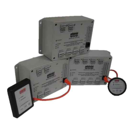
Engine Shutdown Restart
System (ESRS)
Installation Instructions
Owner's Manual
PN: 131-440 (4 Relay Circuits), PN: 131-445 (6 Relay Circuits), and PN: 131-450 (8 Relay Circuits)
Warning: This Sea-Fire Engine Shutdown Restart System has been designed and
tested for use with Sea-Fire automatic and manual fire suppression systems.
Installation must be accomplished by or under the supervision of a qualified marine
electrician who is familiar with American Boat and Yacht Council (ABYC) or other
recognized and accepted marine standards and practices.
Caution: Do not install this device in fuel storage compartments. See the installation
section of this manual for further details.
Read this manual thoroughly and comply with all instructions, warnings, and
cautions prior to installation.
THIS MANUAL IS AN INTEGRAL PART OF THE SYSTEM AND AS SUCH, THE SYSTEM
MUST BE INSTALLED AND MAINTAINED ACCORDINGLY.
RETAIN THIS MANUAL FOR REFERENCE
SEA-FIRE MARINE – USA
SEA-FIRE EUROPE, LTD
Baltimore, Maryland
Hampshire, United Kingdom
Your Onboard Safe Choice
www.sea-fire.com
www.sea-fire.co.uk
A Division of Metalcraft, Inc.
123-567 Rev. A
Advertisement
Table of Contents


Need help?
Do you have a question about the 131-440 and is the answer not in the manual?
Questions and answers