
Summary of Contents for Sterling KA Series
- Page 1 Linear Scales Linear Scales Linear Scales Linear Scales Installation Installation Installation Installation Manual Manual Manual Manual...
- Page 2 STERLING KA Series Glass Scales Sterling’s KA series of glass scales are designed and manufactured to deliver the optimal structure for rigidity with ease of installation and high precision. A modular range of accessory installation brackets make installations fast, easy, and accurate without the need to fabricate on site.
- Page 3 STERLING KA Series Glass Scales 2) Applicable to the TTL signal output of KA-300, KA-500 and KA-600 scales using 9-pin sockets. Signal Null Null Null Null Color Black Green Brown Orange White FG覲connected to metal case for shielding. 3) Applicable to the TTL signal output of KA-300, KA-500 and KA-600 scales with 7-pin sockets.
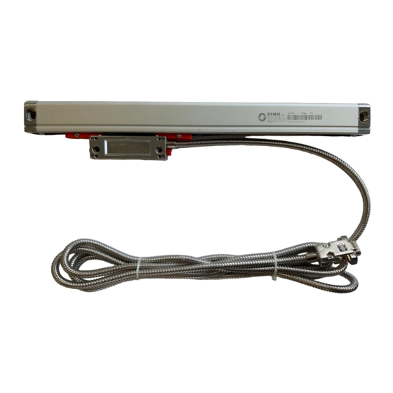
- Page 4 STERLING KA Series Glass Scales 2. Scale Structure: The glass scale is composed mainly of the glass assembly and the reading head assembly (See Fig. 1). KA-300 Installation hole of ruler Sealing rubber End cap assembly of ruler Fastening assembly...
-
Page 5: Full Cover
STERLING KA Series Glass Scales 3.1 Cover Type A, for installation on finished surface, oil resistant and scrap proof (See Fig. 2). 3.2 Cover Type B and H, for installation on finished or unfinished surface, oil resistant and scrap proof, applicable to installation surface shorter than scales, contributive to the scale rigidity (See Fig. -
Page 6: Table Of Contents
STERLING KA Series Glass Scales KA-500覲 Full Cover Semi Cover KA-500-I KA-500-H Fig. 7 Fig. 8 Bearing Plate KA-500-PJ-B Fig. 9 KA-600覲 Semi Cover KA-600-J Fig. 10... -
Page 7: Fig. 11
STERLING KA Series Glass Scales 4. Installation 4.1 Installation Dimension Dimensions of KA-300 glass scale 2-M4 68.0 21.0 68.0 25.0 82.0 Fig. 11 Model Model KA300-70 KA300-570 KA300-120 KA300-620 KA300-170 KA300-670 KA300-220 KA300-720 KA300-270 KA300-770 KA300-320 KA300-820 KA300-370 KA300-870 KA300-420... - Page 8 STERLING KA Series Glass Scales Dimensions of KA-500 glass scale Fig. 12 Model Model KA500-70 KA500-320 KA500-120 KA500-370 KA500-170 KA500-420 KA500-220 KA500-470 KA500-270...
-
Page 9: Fig. 13
STERLING KA Series Glass Scales Dimensions of KA-600 glass scale. 1000 2-M4 1000 Fig. 13 Model Model KA600-1000 1000 1150 1170 KA600-2100 2100 2250 2270 KA600-1100 1100 1250 1270 KA600-2200 2200 2350 2370 KA600-1200 1200 1350 1370 KA600-2300 2300 2450... - Page 10 STERLING KA Series Glass Scales Attentions: The selection of the gauged scale length depends on the travel length of the machine. The gauged scale length must be longer than the maximum travel length of the machine. Proper spare parts shall be adopted according to the given installation length and surface.
- Page 11 STERLING KA Series Glass Scales Fig. 14 4.3 Installation of the Scale and Scale Cover (1) Installation of Scales with Cover Type A a. Choose the proper installation position b. Mark out and drill M4 screw holes on the installation surface according to the given installation length.
- Page 12 STERLING KA Series Glass Scales (2) Installation of Scales with Cover Type C, I and J See Installation of Scales with Cover Type A. Scale with Cover KA-300C: L0+125 Scale with Cover KA-500I: 20.5 L0+134 Scale with Cover KA-600J: L0+240 For installation dimensions, see Fig.
- Page 13 STERLING KA Series Glass Scales scale to the machine’s leading rail, and adjust the parallelism well (See Fig. 16). d. Wrench tight the strengthening plate to the installation surface. e. Install the scale assembly to the strengthening plate. f. Adjust the fastening screws of the reading head till they touch the installation surface.
- Page 14 STERLING KA Series Glass Scales Scale with Cover KA-500G: L0+134 For installation dimensions, see Fig. 17, Fig. 18 and Fig. 19. KA-300覲 Fig. 17 27.8 28.4 KA-500: 20.5 28.4 Fig. 18...
- Page 15 STERLING KA Series Glass Scales KA-600覲 Fig. 19 4.4 Installation of the Reading Head The reading head can be installed on finished or unfinished surface in a normal or converse way. Only in case of limited installation space, can it be installed conversely.
- Page 16 STERLING KA Series Glass Scales Adjusting Screw Unfinished Installation Surface Adjusting Screw Fig. 21 Fig. 20 14 0.075 68 0.15 Plate A of T Frame 68 0.15 14 0.075 68 0.15 Plate B of T Frame 2_M5 Extension Plate C of T Frame 2_§...
- Page 17 STERLING KA Series Glass Scales A+C+B A+D+B Fig. 22 Fig. 23 Fig. 24 Fig. 25 Fig. 27 Fig. 26 Figures above applicable to installation of KA-300 and KA-600 scales...
- Page 18 STERLING KA Series Glass Scales A+C+E B+C+E Fig. 28 Figures above applicable to installation of KA-300 and KA-600 scales Fig. 29 Fig. 30 A+A+C+B A+A+D+B Fig. 31...
- Page 19 STERLING KA Series Glass Scales Figures above applicable to installation of KA-300 and KA-600 scales 4.5 Rearrangement of Reading Head Cable The cable of the reading head is arranged on the right in the factory. If it is inconvenient for use, the user may rearrange it in another direction in the following procedure: (1) Take out four M2 “+”...
- Page 20 STERLING KA Series Glass Scales 5. Checking installation 5.1 With the reading head securely fastened, if you shake it headlong, position display may fluctuate while shaking, but will always return to the same stable value if left alone. 5.2 The reading head should be centered in the scale body to ensure proper sealing as shown in Fig32, Fig 33 and Fig 34.
Need help?
Do you have a question about the KA Series and is the answer not in the manual?
Questions and answers