
Related Manuals for AMX AXB-TMC

Summary of Contents for AMX AXB-TMC
-
Page 1: Instruction Manual
AXB-TMC/TMX+ Television Managers A X l i n k B u s C o n t r o l l e r s... - Page 2 This warranty extends only to products purchased directly from AMX Corporation or an Authorized AMX Dealer. AMX Corporation is not liable for any damages caused by its products or for the failure of its products to perform. This includes any lost profits, lost savings, incidental damages, or consequential damages. AMX Corporation is not liable for any claim made by a third party or by an AMX Dealer for a third party.
-
Page 3: Table Of Contents
Programming ...19 Channel Setting Commands ... 19 IR Functions (Synergy System Standard Order)... 20 System Send_Commands... 21 AXB-TMC Clock Send_Commands ... 26 Using the ASCII character set for scrolling displays ... 28 RS-232 Request Commands ... 30 AXB-TMC/TMX+ Television Managers... - Page 4 Table of Contents Response Mask ... 31 RS-232 Response Commands ... 31 RS-232 Send_Commands ... 32 Troubleshooting ... 35 AXB-TMC/TMX+ Television Managers...
-
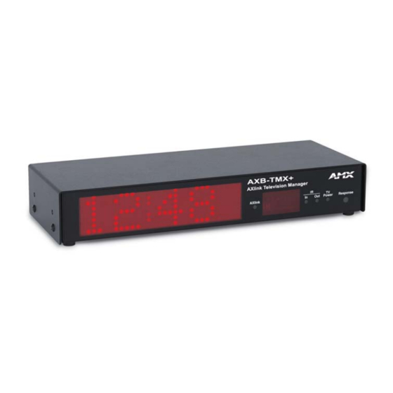
Page 5: Product Information
AXlink bus or for direct RS-232 control via a PC or other controller. As part of an Axcess Control System, they provide media source selection and management via remote control. The AXB-TMC/TMX+ acts as a local Axcess controller and as a receiver for an AMX wireless control panel. -
Page 6: Specifications
IR In LED (Red) Flashes when the AXB-TMC/TMX+ receives an IR signal from a wireless trans- IR Out LED (Red) Flashes when the AXB-TMC/TMX+ IR port sends and IR command to the tele- TV Power LED (Red) Lights when the CC-XPS External Frequency Television Scan Sensor detects... -
Page 7: Setting Dip Switches
Axcess can control up to 255 AXlink devices; each device is assigned a device number in the Axcess program. AMX standard device numbers for interface bus devices are 96 - 127. (Axcess cards are in the range from 1 to 95, and control panels are in the range of 128 - 255.) Set the device number on the AXB-TMC/TMX+ to match the device assignment in the Axcess program. - Page 8 Product Information FIG. 2 shows the Auxiliary DIP switch for the AXB-TMC/TMX+. The following tables display the DIP switch settings and functions for switches 1 through8. 1 2 3 4 5 6 FIG. 2 Auxiliary DIP switch Auxiliary DIP Switch Settings 1 - 5 and...
- Page 9 Product Information FIG. 3 shows the location of the jumpers on the AXB-TMC/TMX+ circuit boards. Jumpers J1 and J2 select AXlink or RS-232 communications, and J4 sets the I/O pull-up voltage to either 5 VDC or 12 VDC. JP1 JP2 JP4...
- Page 10 Product Information AXB-TMC/TMX+ Television Managers...
-
Page 11: Installation
Installation Do not connect power to the AXB-TMC/TMX+ until the wiring is complete. If you are using power from AXlink, disconnect the wiring from the Central Controller before wiring the AXB-TMC/TMX+. The AXB-TMX+ and AXB-TMC cover accepts an optional security bracket. Once the optional security bracket is installed, it restricts tampering with the serial data, I/O control, IR emitter, AXlink, and 12 VDC power wiring. -
Page 12: Tv Sensor Connections
FIG. 6. FIG. 6 Removing factory installed shell 2. Test-fit the IR shield (FIG. 7) to the television's IR window. If necessary, use scissors and trim the shield to fit. FIG. 7 IR shield CC-XPS Television CC-IRC Television AXB-TMC/TMX+ Television Managers... -
Page 13: Axlink Data And Power Connections
AXlink Data and Power Connections Connect the Central Controller's AXlink connector to the AXlink connector (male) on the rear panel of the AXB-TMC/TMX+ for data and 12 VDC power, as shown in FIG. 9. Optional shield FIG. 9 AXlink wiring diagram... -
Page 14: Axlink Data And 12 Vdc Power Supply Connections
Connect the optional PCS, as shown in FIG. 11, for automated power control using Send_Commands PON and POF. A PIN command must be sent to the AXB-TMC/TMX+ either from terminal mode or from within an Axcess program. If PIN is not used, the PCS state is received as... -
Page 15: Pc1 Connections
IR signal generated by the AXB-TMC/TMX+. You can reset switches 1 - 5 on the Auxiliary DIP switch to decrease the strength of the IR signal. Refer to the Auxiliary DIP switch on page 3 and the Auxiliary DIP Switch Settings 1 - 5 and Values for IR/serial table on page 4. -
Page 16: Television Power Receiver (Cc-Xps) Adjustment
To install the angle brackets on the AXB-TMC/TMX+: 1. Position the side of the angle-mounting bracket (with two holes) against the side of the AXB-TMC/TMX+. Then, align the two bracket holes with the two threaded screw holes in the side of the AXB-TMC/TMX+. -
Page 17: Detachable Mounting
Self-adhesive Velcrop strips can be mounted to the top or bottom of the unit's housing for surface mounting, or the flush-mount brackets. The following steps explain how to mount the AXB-TMC/TMX+ to a flat surface, after installation of the angled mounting brackets to the unit, using self-adhesive Velcro. -
Page 18: Rack-Mount Installation
Installation Rack-mount installation Rack-mounting the AXB-TMC/TMX+ requires an optional TMX-RK Rack Kit. Refer to FIG. 15 and the following steps to mount the AXB-TMC/TMX+ in a rack. & FIG. 15 AXB-TMC/TMX+ rack mount installation 1. Position the short mounting bracket mounting holes in the bracket with the threaded holes in the AXB-TMC/TMX+. - Page 19 7. Position the AXB-TMC/TMX+ in the equipment rack and secure it using four #10-32 x 5/8" truss screws The following table lists the contents of the TMX-RK Rack Kit. TMX-RK Rack Kit Contents Item No. Item (FIG. 15) Rack-mount bracket (long)
- Page 20 Installation AXB-TMC/TMX+ Television Managers...
-
Page 21: Upgrading The Firmware
RAM to flash memory, the unit will not operate at all when power returns. If you have not already installed the SOFTROM program, do so by following the steps contained on the AMX Control Disc. Configuration To configure the communication setting for the SOFTROM program: 1. - Page 22 Upgrading the Firmware AXB-TMC/TMX+ Television Managers...
-
Page 23: Programming
Response LED lights when channel is on. AXB-TMC Only: A push and release on this channel indicates that a scroll has completed. This occurs after all the trailing blanks (plus one) have scrolled off the display. -
Page 24: Ir Functions (Synergy System Standard Order)
Video1, Line A, VCR1, VDP, or input + Video2, Line B, VCR2, or input - Video3 RGB1 or Tape1 RGB2 or Tape2 TUNER PHONE AM/FM PLAY < (play reverse) TV/Video (Input 1) TV/Video (Input 2 SAP (Input 3) Input 4 Input 5 AXB-TMC/TMX+ Television Managers... -
Page 25: System Send_Commands
'?CTOF' Example: SEND_COMMAND AXBTMX,'?CTOF' Sends the current off-time pulse string from the AXB-TMC/TMX+ to the Central Controller in the CTOF <Time> format. All ? (request) Send_ Commands respond with strings to the Central Controller. If an RS-232 device connected to the AXB-TMC/TMX+ is... - Page 26 Sets the pulse length to 2 seconds on the AXB-TMC/TMX+. Syntax: '?CTON' Example: SEND_COMMAND AXBTMX,'?CTON' Sends the current on-time pulse string from the AXB-TMC/TMX+ to the Central Controller in the CTON <Time> format. Syntax: "'DC',<IR in>,<IR out>" Variables: <IR in> = custom IR functions assigned to hand-held IR transmitting device.
- Page 27 Disables current PON or POF command settings. Sends IR function 28 to turn device power off. Sends IR function 27 to turn device power on. AXB-TMC/TMX+ Television Managers Syntax: 'DK' Example: SEND_COMMAND AXBTMX,'DK' Deletes all direct connections set with the DC command.
- Page 28 PTON sets the pulse length for all power pulses, regardless if the pulse is due to a PON or POF command. Example: SEND_COMMAND AXBTMX,"'PTON',20" Sets the IR power pulse on time (delay) to 2 seconds for the AXB-TMC/TMX+. Syntax: '?PTON' Set the <Time> value in .10 second increments.
- Page 29 <IR out> = 1 through 127. (See IR functions table on page 20 for standard IR functions.) Example: SEND_COMMAND AXBTMX,"'SP',25" Pulses IR code 25 which decreases the volume level on the equipment con- nected to the AXB-TMC/TMX+. Syntax: 'XCHM-<Channel mode>' Variables: <Channel mode> = Mode 0 through 3: Mode 0: [x][x]<x><enter>...
-
Page 30: Axb-Tmc Clock Send_Commands
Programming AXB-TMC Clock Send_Commands Clock Send_Commands are unique to the AXB-TMC only. These commands are stored in the Axcess Central Controller and are used to control clock-timing functions. 12-hour format is the default time format AXB-TMC Clock Send_Commands BRIGHT Displays brightness. - Page 31 Spaces will be added by the AXB-TMC when the total scroll length is less than a multiple of eight. (Refer to the Using the ASCII character set for scrolling displays on section page 28.)
-
Page 32: Using The Ascii Character Set For Scrolling Displays
STOPCT Stops active countdown timer. STOPSTP Stops the stopwatch. Using the ASCII character set for scrolling displays The ASCII character set is used with the Send_Commands for the AXB-TMC/TMX+. ASCII Character Set Name null start of heading start of text... - Page 33 This will result in a display of - I don't understand. The curly braces ({ and }) display degrees Fahrenheit and degrees Centigrade. An example is: SEND_COMMAND TMC, 'SCROLL-Temperature 66 {' The AXB-TMC recognizes the { as temperature Fahrenheit and will display 66°F. AXB-TMC/TMX+ Television Managers Char Char <...
-
Page 34: Rs-232 Request Commands
"'*', 5, 3, 9, 'PON', 0" This 'PON' command is sent to the AXB-TMC/TMX+. Syntax: '*'<8><CHECKSUM> Example: "'*', 8, 50" Requests bus status. The AXB-TMC/TMX+ responds with a BUS STATUS string. Syntax: '*'<9><CHECKSUM> Example: "'*', 9, 51" Requests the devices and device numbers of the AXB-TMC/TMX+. The AXB-TMC/TMX+ responds with a DEVICE LIST string. -
Page 35: Response Mask
Response Mask By default, data is sent when the AXB-TMC/TMX+ gets changed. Bits in the response mask can turn off the sending of this data: (1=ON), the data is sent. (0=OFF), the data is not sent. Response Mask Data Controlled... -
Page 36: Rs-232 Send_Commands
Programming RS-232 Send_Commands RS-232 Send_Commands are also stored in the Axcess Central Controller and direct the AXB-TMC/TMX+ to perform various operations using an RS-232 communication protocol. RS-232 Send_Commands Eliminates the two bar code bytes attached to every incoming string over the RS232 port. - Page 37 AXB-TMC/TMX+ Television Managers Syntax: "'SU',<value>" Variable: <Value> = See FIG. 16 and the following tables. Example: SEND_COMMAND AXBTMX,"'SU',255" Sets the AXB-TMC/TMX+ communication settings to 38, 4K baud, no parity, 8 data bits, 1 stop bit. Parity Data Value 1 bit 2 bits...
- Page 38 The following table shows common hexadecimal and decimal value settings used with the SU command. Common Settings Baud Parity 1,200 Even 9,600 Even 38,400 Even 1,200 None 9,600 None 38,400 None Bits Data Stop Binary value Hex value 01010101 10110101 11110101 01011111 10111111 11111111 Decimal value AXB-TMC/TMX+ Television Managers...
-
Page 39: Troubleshooting
IR Functions Map in this manual. If the AXB-TMC/TMX+ does not have codes loaded, or the loaded codes do not appear to be correct, reload the proper codes. Refer to the IRLIB Infrared Library Management Program instruction manual for additional information. - Page 40 Resolution The AXB-TMC/TMX+ does output IR pulses, but the TV/projector does not always respond. In this case, the PTON pulse is too short. Extend the PTON pulse by entering the following via the terminal mode: >CHANGE PTON 10 71...
- Page 41 Verify that the baud rate and other information is set properly for the device connected to the AXB-TMC/TMX+. This is a bad AXB-TMC/TMX+ device or bad wiring within the AXlink cable. To quickly verify the wiring, install a working AXB-TMC/TMX+ in place of the sus- pect device.
- Page 42 AMX reserves the right to alter specifications without notice at any time. brussels • dallas • los angeles • mexico city • philadelphia • shanghai • singapore • tampa • toronto* • york 3000 research drive, richardson, TX 75082 USA • 469.624.8000 • 800.222.0193 • fax 469.624.7153 • technical support 800.932.6993...
Need help?
Do you have a question about the AXB-TMC and is the answer not in the manual?
Questions and answers