
Related Manuals for All Weather Inc 20981

Summary of Contents for All Weather Inc 20981
- Page 1 Model 20981 UHF Data Radio User’s Manual Rev. A All Weather Inc. • 1065 National Drive • Sacramento, CA 95834 • USA • 800.824.5873 • www.allweatherinc.com...
- Page 2 Copyright © 2020, All Weather, Inc. All Rights Reserved. The information contained herein is proprietary and is provided solely for the purpose of allowing customers to operate and/or service All Weather, Inc. manufactured equipment and is not to be released, reproduced, or used for any other purpose without written permission of All Weather, Inc. Throughout this manual, trademarked names might be used.
- Page 3 Model 20981 UHF Data Radio User’s Manual Revision History Revision Date Summary of Changes 2020 Feb 15 Initial release.
-
Page 5: Table Of Contents
Model 20981 UHF Data Radio User’s Manual TABLE OF CONTENTS OVERVIEW ......................... 1 1.1 Installation Kits ........................... 1 1.2 FCC Regulations ......................... 1 1.2.1 Licensing ..........................1 1.2.2 Equipment Authorization (Certification) ................1 1.2.3 Radio Frequency Exposure ....................2 I/O CONNECTOR AND LED INDICATORS ................ 3 2.1 I/O Connector .......................... -
Page 6: Overview
1.1 INSTALLATION KITS Kits have been prepared to allow the Model 20981 UHF Data Radio to be installed in an AWOS 3000 CDP, a DCP, or as a retrofit to a previous installation using other radio modems. The kits provide the UHF Data Radio(s), attenuator, other hardware, and cables needed for the installation. -
Page 7: Radio Frequency Exposure
The Model 20981 UHF Data Radio has been evaluated for compliance with the maximum exposure limits for RF energy at the maximum power rating of the unit. To ensure compliance with the General Population/Uncontrolled maximum exposure limits, please ensure that all persons will be at least 20.5 cm (8.1") away from the antenna. -
Page 8: I/O Connector And Led Indicators
Model 20981 UHF Data Radio User’s Manual 2. I/O CONNECTOR AND LED INDICATORS 2.1 I/O CONNECTOR Table 2. I/O Connector Pinout Name Description Comments — — Not used — — Not used — — Not used Input Channel 1/2 or High/Low power... - Page 9 Model 20981 UHF Data Radio User’s Manual Pin 6 (Supply) Pin 6 is the positive power supply input for the modem. Pin 7 (Receiver Alignment) Pin 7 is the output pin of the modem IC’s input operational amplifier. It is used during alignment to set the receiver gain and DC offset for proper modem IC receiver decoding.
-
Page 10: Led Indicators
User’s Manual 2.2 LED INDICATORS The Model 20981 UHF Data Radio has two LEDs on the side of the unit, one green RX LED and one red TX LED. • The GREEN RX LED can be programmed to be illuminated under a variety of conditions. -
Page 11: Operation
3. OPERATION 3.1 CHANNEL SELECTION The Model 20981 UHF Data Radio supports one channel if the A/B pin (pin 4) is programmed for high/low power and two channels if the A/B pin is programmed as a channel select input. Channel A is set when the A/B pin is activated and the A/B pin is in the logic high state, i.e., above 2.0 VDC or is left unconnected. -
Page 12: Duty Cycle/Key-Down Limitations
Duty Cycle (%) Key-Down Time (s) The operation of the Model 20981 UHF Data Radio in All Weather Inc. AWOS systems will be within these limits. Blowing air across the unit and/or adding a heat sink to the rear of the unit where the PA module... -
Page 13: Installation
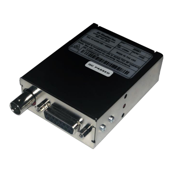
User’s Manual 4. INSTALLATION The Model 20981 UHF Data Radio has two connectors, a female BNC connector for the RF (antenna) connection and a 15-pin D-subminiature for the data/programming interconnection. Connect the BNC connector to a suitable antenna or RF dummy load or attenuator, depending on the installation. -
Page 14: Programming The Data Radio
Use the PCPS programming utility to configure and adjust the operating parameters of Model 20981 UHF Data Radio. Load the programming utility on a host computer. If the utility does not install automatically, it can be started manually by running “Setup.exe”. -
Page 15: Frequency Tab
Model 20981 UHF Data Radio User’s Manual 5.1 FREQUENCY TAB Click the “Read Radio” button. The Frequency tab will open. his page shows the frequencies programmed into the Data Radio. Depending on how the A/B pin is programmed, either one or two pairs of frequencies will be displayed. Frequencies can be programmed into the device by clicking on the appropriate field and typing in the desired frequencies. -
Page 16: General Tab
Model 20981 UHF Data Radio User’s Manual • Monitor is a software (programmer) Monitor selection. Selecting this button will unmute the analog/voice receiving path of the Data Radio. Selecting this button again will return the radio back to normal squelched operation. Note that if unsquelched operation is selected on the Analog page, this button will have no effect. -
Page 17: Modem Page
The Modem tab allows the selection of the parameters of the Data Radio mode operation. • Modem Protocol selects the over-the-air protocol. Although there are three choices, only the last one applies to the Model 20981 Data Radio. Protocol 2.00 (Legacy) is a very robust packet protocol useful for large data... - Page 18 Model 20981 UHF Data Radio User’s Manual • Test Patterns (via Test Pin) Selecting any of the selections in this box will cause a test pattern to be transmitted when the Test Pin (PTT) is active. If no selection is made, activating the Test Pin will cause the Data Radio to transmit in analog/voice mode.
-
Page 19: Analog Tab
Model 20981 UHF Data Radio User’s Manual o Partial Packet Timeout The amount of time in ms of no data from the data device that must exist before a packet is formed and transmitted. 5.3 ANALOG TAB The Analog tab allows selection of the analog/voice mode parameters. -
Page 20: Summary Tab
2. Saving all except the squelch and RF power level (useful if the Data radio already has power and squelch settings that are to be retained) 3. Convert older DTXM-X54 series products to the configuration of the Series II modems (not used for the Model 20981 UHF Data Radio) - Page 21 Model 20981 UHF Data Radio User’s Manual...
-
Page 22: Awos Installation
6. AWOS INSTALLATION 6.1 DCP INSTALLATION The Model 20981 UHF Data Radio is mounted on a DIN rail on the DCP backplane and is connected to the DCP Sensor Interface board. Refer to the Model 1190 DCP User's Manual for installation instructions. -
Page 23: Maintenance
Model 20981 UHF Data Radio User’s Manual 7. MAINTENANCE When the Model 20981 UHF Data Radio is installed in an AWOS, periodic maintenance and verification must be carried out according to a schedule that includes monthly, triannual, and annual procedures. -
Page 24: Triannual Maintenance
Model 20981 UHF Data Radio User’s Manual 7.1.2 Triannual Maintenance Perform the monthly maintenance. No additional procedures are required. 7.1.3 Annual Maintenance Annual maintenance and validation both the CDP and the DCP radios consists of the following tests. • Power level •... - Page 25 Model 20981 UHF Data Radio User’s Manual Sample Calculation: Reflected power = 0.02 W Forward power = 2.5 W reflected power forward power 0894 0894 VSWR 1964 − − 0894 9106 reflected power − − forward power 7.1.3.3 Frequency 1. Replace the power element with the RF sampler element.
-
Page 26: Specifications
Model 20981 UHF Data Radio User’s Manual 8. SPECIFICATIONS Parameter Specification FCC Identifier AIERIT39-46006 Regulatory Approvals Industry Canada Identifier 1084A-RIT394 Frequency Range 450–470 MHz Channel Width 12.5 kHz Data Rate 9600 bps Modulation 4FSK Channels Operating Bandwidth 20 MHz Synthesizer Step Size 5.0/6.25 kHz... - Page 27 Model 20981 UHF Data Radio User’s Manual Parameter Specification Power and Mechanical Supply Voltage 11–16 VDC, up to 3 A in Transmit mode RF Connector Power/Data Connector 15-pin subminiature D-type 91 mm L × 58 mm W × 25 mm H Dimensions (3.6"...
-
Page 28: Warranty
Any defect in design, materials, or workmanship which may occur during proper and normal use during a period of 1 year from date of installation or a maximum of 2 years from shipment will be corrected by repair or replacement by All Weather Inc. - Page 29 All Weather Inc. 1065 National Drive, Suite 1 Sacramento, CA 95818 20981-001 Fax: 916.928.1165 Revision A Phone: 916.928.1000 February, 2020 Toll Free: 800.824.5873...
Need help?
Do you have a question about the 20981 and is the answer not in the manual?
Questions and answers