Table of Contents
Advertisement
Quick Links
CZ-200P
Instruction Manual
Thank you for purchasing this RKC product. In order to achieve maximum
performance and ensure proper operation of your new instrument, carefully
read all the instructions in this manual. Please place the manual in a
convenient location for easy reference.
CONTENTS
1. OUTLINE ··············································································································· 1
2. PRODUCT CHECK ······························································································· 2
3. HANDLING OF THE PRESSURE SENSOR ························································· 2
3.1 Caution in Mounting Pressure Sensors······························································ 2
3.2 Caution in Removing Pressure Sensors ···························································· 4
3.3 Cautions during Extruder Cooling Down ···························································· 4
3.4 Caution in Handling of Built-in Thermocouple ···················································· 4
3.5 Dimensions ········································································································ 4
3.6 Pressure Sensor Installation ·············································································· 5
4. WIRING ················································································································· 5
4.1 Wiring Precaution ······························································································· 5
4.2 Wiring Method ···································································································· 6
5. ADJUSTMENT ······································································································· 7
6. CORRECTION ······································································································· 8
6.1 Correcting Indication Error due to the Operating Temperature ·························· 8
6.2 Correcting Indication Error due to the Connection Cable Length ······················ 8
6.4 Correcting Indication Error due to the Safety Barrier ········································· 8
7. TROUBLESHOOTING ··························································································· 9
8. SPECIFICATIONS ································································································· 9
9. EXPLANATION OF EACH TERMS ····································································· 10
SYMBOLS
:
This mark indicates precautions that must be taken
WARNING
if there is danger of electric shock, fire, etc., which
could result in loss of life or injury.
:
This mark indicates that if these precautions and
CAUTION
operating procedures are not taken, damage to the
instrument may result.
:
!
This mark indicates that all precautions should be
taken for safe usage.
:
This mark indicates important information on
installation, handling and operating procedures.
:
This mark indicates supplemental information on
installation, handling and operating procedures.
:
This mark indicates where additional information
may be located.
!
An external protection device must be installed if failure
of this instrument could result in damage to the
instrument, equipment or injury to personnel.
All wiring must be completed before power is turned on
to prevent electric shock, fire or damage to instrument
and equipment.
This instrument must be used in accordance with the
specifications to prevent fire or damage to instrument
and equipment.
This instrument is not intended for use in locations
subject to flammable or explosive gases.
Do not touch high-voltage connections such as power
supply terminals, etc. to avoid electric shock.
RKC is not responsible if this instrument is repaired,
modified
or
disassembled
factory-approved personnel. Malfunction can occur and
warranty is void under these conditions.
CAUTION
This product is intended for use with industrial machines, test
and measuring equipment. (It is not designed for use with
medical equipment and nuclear energy.)
All Rights Reserved, Copyright © 1998, RKC INSTRUMENT INC.
IM100CZ08-E9
WARNING
by
other
®
This is a Class A instrument. In a domestic environment, this
instrument may cause radio interference, in which case the user
may be required to take additional measures.
All precautions described in this manual should be taken to avoid
damage to the instrument or equipment.
All wiring must be in accordance with local codes and regulations.
Tighten each terminal screw to the specified torque found in the
manual to avoid electric shock, fire or malfunction.
Remove resin adhered to the instrument with dry cloth before the
resin hardens. Take caution to avoid being burned.
Tools such as wire wheels or abrasive cloths should never be
used to clean the process diaphragm.
Dropping the instrument may cause the sensor to break or
malfunction.
To protect built-in precision components from damage, handle and
install carefully. Take care to avoid damage to the diaphragm.
Do not wipe or rub the nameplate on the outer case of the resin
pressure sensor with a cloth moistened with an organic solvent, or
a glove. If so, the printed section may be erased.
This product uses stainless steel, aluminum, and fluororesin (O-rings
and leadwire covering materials). When disposing of each part used
for this product, always follows the procedure for disposing of industrial
wastes stipulated by the respective local community.
If the output from the resin pressure sensor is found to be
abnormal during the operation, immediately stop the operation and
inspect for any distortion or damage of the diaphragm. If the
diaphragm is damaged, the pressure of the measured media
(e.g.resin) is applied to the inside of the resin pressure sensor.
Continued use under such conditions may result in the damage of
the screw which fixes the folder in the housing, and the folder in
the housing may come off in the worst case.
Do not use the pressure sensor in stead of a blind bolt.
This manual assumes that the reader has a fundamental knowledge
of the principles of electricity, process control, computer technology
and communications.
The figures, diagrams and numeric values used in this manual are
only for purpose of illustration.
RKC is not responsible for any damage or injury that is caused as a
result of using this instrument, instrument failure or indirect damage.
RKC is not responsible for any damage and/or injury resulting
from the use of instruments made by imitating this instrument.
Periodic maintenance is required for safe and proper operation of
this instrument. Some components have a limited service life, or
characteristics that change over time.
Every effort has been made to ensure accuracy of all information
contained herein. RKC makes no warranty expressed or implied,
with respect to the accuracy of the information. The information in
this manual is subject to change without prior notice.
No portion of this document may be reprinted, modified, copied,
transmitted, digitized, stored, processed or retrieved through any
mechanical, electronic, optical or other means without prior written
approval from RKC.
1. OUTLINE
Great features
• As its lead pipe and pressure sensing blocks have a triple
construction output indication changes caused by external transient
temperature variations are extremely small. In addition, the
attachment of a lead pipe cover (optional) further restricts small
output indication changes.
• As the sensor uses the push rod method, resin contamination is
prevented for the sensor damage.
• High accuracy of the measured pressure can be achieved when the
instrument is used in conjunction with an output converter having
linearizing function (PCT-300) or a pressure indicator (PG500 or
REX-PG410). However, excluding the sensor having pressure
range (70 MPa or more) and a HASTELLOY C diaphragm.
Overall accuracy: ±0.5 % of full scale or less
4-core sielded cable
than
or
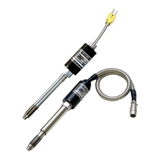
Pressure sensor
CZ-200P
RKC INSTRUMENT INC.
NOTICE
PCT-300
0 to 10 V
0 to 10 mV
1 to 5 V
4 to 20 mA
PG500 or
REX-PG410
0 to 10 V
0 to 10 mV
0 to 2 V
0 to 5 V
1 to 5 V
4 to 20 mA
0 to 20 mA
Indicator
Alarm
Recorder
Pressure
controller
Advertisement
Table of Contents

Related Manuals for RKC INSTRUMENT CZ-200P

Summary of Contents for RKC INSTRUMENT CZ-200P
-
Page 1: Table Of Contents
Pressure sensor 4 to 20 mA CZ-200P and measuring equipment. (It is not designed for use with 0 to 20 mA Pressure medical equipment and nuclear energy.) controller All Rights Reserved, Copyright © 1998, RKC INSTRUMENT INC. RKC INSTRUMENT INC. ®... -
Page 2: Resin Pressure Sensor
2. PRODUCT CHECK Before using this product, check each of the following: (10) Temperature sensor • Model code (Equivalent to IEC 60584-2, Tolerance class 2, 1.0: 1982 b) • Check that all of the items delivered are complete. N: None •... - Page 3 Do not wind sealing tapes, etc. round this section for preventing oil or resin leakage. • When the diaphragm at the end of CZ-200P and its surroundings completely touch with its mounting hole, large indication error may occur. In this case, temperature may exert a large influence especially upon the zero point.
-
Page 4: Caution In Removing Pressure Sensors
A class 2 thermocouple (classification of tolerance: Equivalent to IEC 60584-2, Tolerance class 2, 1.0: 1982 b) is used in the thermocouple temperature sensing block. 3.5 Dimensions Fixed nut type (CZ-200P-H type) E xternal dim ensions M ounting hole dimensions L2−2... -
Page 5: Pressure Sensor Installation
Dimensions of lead pipe cover (Optional) Approx.530 g inserted. Fixed nut type with directly connected cable (CZ-200P-H type) When the material of the diaphragm is SUPRON, only a fixed nut type with directly connected cable is available. External dim ensions... -
Page 6: Wiring Method
Install the power cable away from the 4-conductor shielded cable. Wiring example of standard type • Wiring with PCT-300 (output converter) PCT-300 Terminal No. Shield SHD (E) EXC + (A) Pressure sensor (CZ-200P) Pressure sensor cable Input terminals Brown EXC − (C) Blue SIG + (D) Black SIG −... -
Page 7: Adjustment
1. Check the rated output (mV/V) described on the nameplated of Signal circuit (Polarity +, color of lead covering material: blue) the CZ-200P (This output should be corrected when the cable is Signal circuit extended.) and then set that value on the rotary switch which is (Polarity −, color of lead covering material: black) -
Page 8: Correction
1 % of span. However, when this error needs to be lessened further, make the correction, it RKC Instrument’s resin pressure sensor is calibrated for the necessary. For this correction, the barrier correction factor B is used. -
Page 9: Troubleshooting
• No zero adjuster adjusted.• adhered to its surface due to the removal of the sensor while the resin is not yet melted or its melted condition is imperfect. • Irregularly tapped hole for installing the CZ-200P. No pressure is Protrusion... -
Page 10: Explanation Of Each Terms
The ninth edition: OCT. 2011 [IMQ00] Company names and product names used in this manual are the trademarks or registered trademarks of the respective companies. HEADQUARTERS: 16-6, KUGAHARA 5-CHOME, OHTA-KU TOKYO 146-8515 JAPAN RKC INSTRUMENT INC. PHONE: 03-3751-9799 (+81 3 3751 9799) E-mail: info@rkcinst.co.jp ®...
Need help?
Do you have a question about the CZ-200P and is the answer not in the manual?
Questions and answers