Advertisement
Quick Links
Advertisement

Summary of Contents for Formax CJ-10
- Page 1 CJ-10 / FD 282-30 Conveyor Stacker CJ-15 1000 Watt Dryer OPERATION MANUAL 6/2017 Rev 3...
- Page 3 TABLE OF CONTENTS SPECIFICATIONS UNPACKING CONVEYOR ASSEMBLY OPTIONAL Cj-15 1K DRYER INSTALLATION...
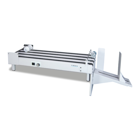
- Page 5 SPECIFICATIONS CONVEYOR POWER 115 VAC 50/60 HZ MAIN FUSE 10 AMP / 250V SECONDARY FUSE 1 AMP / 250V BELT SPEED VARIABLE, 0 TO 124 FT PER MINUTE DIMENSIONS WITH DROP TRAY 51” - 59” L x 12.5” W x 5.5”-8.5” H from top of deck to bottom of tray DROP TRAY CAPACITY 8”...
- Page 6 2. Infeed roller assembly 3. Back infeed guide 4. Front infeed guide CJ-10 Leg 282-30 Leg Install the infeed and exit roller assemblies. First install the infeed roller guides. Turn the conveyor on its side, then using the Allen wrench supplied, remove the four Button Head Allen screws from the infeed end of the conveyor (Fig 1a).
- Page 7 4. Install the out-feed panel (Fig 2), using five Button Head (short) screws and the Allen wrench supplied with unit. Attach the side guide and backstop to the tray and then mount to the out-feed panel by sliding the tabs of the tray into the slots on the panel, as shown in Fig 3.
- Page 8 OPTIONAL DRYER INSTALLATION Place conveyor on its side, and remove button head screws (4 each) from the bottom pan. Install the dryer stand brackets using the screws that were removed (Fig 5). Dryer Mounting Shafts E-clips E-clips Button Head Screws Stand Brackets Fig 5 Place conveyor upright and slide dryer shafts through holes in dryer assembly.
Need help?
Do you have a question about the CJ-10 and is the answer not in the manual?
Questions and answers