Table of Contents
Advertisement
Advertisement
Table of Contents

Subscribe to Our Youtube Channel
Related Manuals for biosystems A25


Summary of Contents for biosystems A25
- Page 1 SERVICE MANUAL ENGLISH...
- Page 3 SERVICE MANUAL English TESE-00001-04-ENG June - 2006...
-
Page 5: Table Of Contents
TABLE OF CONTENTS 1. INTRODUCTION ................. 9 1.1. GENERAL DESCRIPTION OF THE ANALYZER ............9 1.1.1. Operating arm ............................10 1.1.2. Dispensing system ..........................10 1.1.3. Reactions rotor and reading ........................11 1.1.4. Electronic system ..........................12 1.1.5. Application program ........................... 12 1.2. - Page 6 Service Manual 4.2.3. Adjustment of the positioning of the operating arm ................ 67 4.2.3.1 Adjusting the maximum sweep of the Z axis.................. 67 4.2.4. Adjustment of the positioning of the rotor ..................69 4.2.4.1. Centering of the rotor with regard to the dispensing point ............69 4.2.4.2.
- Page 7 5.1.1.3. Removing the main cover ......................100 5.1.1.4. Removing the back housing ......................101 5.1.1.5. Removing the main cover hinges ....................102 5.1.2. Operating arm ............................ 102 5.1.2.1. Fully removing the operating arm ....................102 5.1.2.2. Changing the cable carrier chain with the electrical hoses and dispensing tube ....102 5.1.2.3.
- Page 8 Service Manual 5.3.1. General care of the analyzer ......................129 5.3.2. Cleaning the optical system ......................129 5.3.3. Cleaning the dispensing system ...................... 130 5.3.4. General cleaning of the interior of the apparatus ................. 130 A I. TECHNICAL SPECIFICATIONS ........... 131 A II.
-
Page 9: Introduction
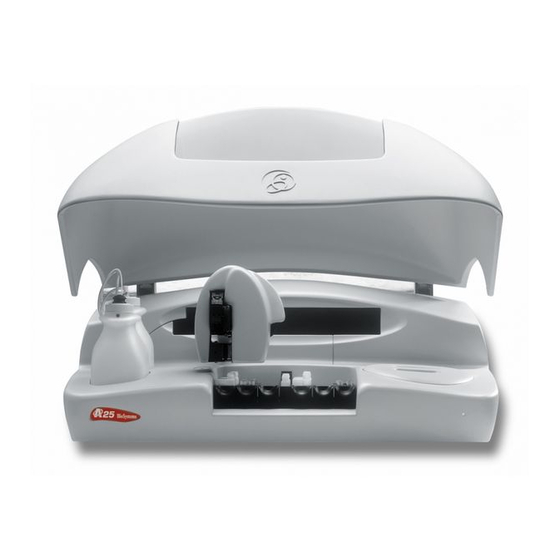
1.1. GENERAL DESCRIPTION OF THE ANALYZER The A25 analyzer is made up of three basic components: the operating arm, the dispensing system and the reading and reactions rotor. The electronic system of the instrument controls said components and communicates with the external... -
Page 10: Operating Arm
The A25 analyzer has a tray with 6 free positions for racks of reagents or samples, plus three fixed positions for bottles opposite the washing station. Each reagents rack can carry up to 10 reagents in 20 ml or 50 ml bottles. Each samples rack can contain up to 24 tubes of samples. -
Page 11: Reactions Rotor And Reading
(120 samples) to 5 racks of reagents (50 reagents) and 1 rack of samples (24 samples). Any reagent may be placed in the fixed positions, but it is recommendable to use them for the bottles of distilled water, saline solution for the automatic pre-dilutions and washing solution. -
Page 12: Electronic System
Service manual The optical system continues to work when the general cover of the analyzer is open, whereby the analyzer can continue to take readings while the user handles, for example, the sample tubes or the reagent bottles. The rotor cover must be in place for the optical system to work correctly. -
Page 13: Functioning Of The Analyzer
1.2. FUNCTIONING OF THE ANALYZER The A25 analyzer is an automatic random access analyzer specially designed for performing biochemical and turbidimetric clinical analyses. The analyzer performs patient-by-patient analyses and enables the continual introduction of samples. The analyzer is controlled from a dedicated PC that is permanently communicated to the instrument. The program, installed on the computer, keeps the user constantly informed of the status of the analyzer and the progress of the analyses. - Page 14 Service manual Screws (1) and (2) are for blocking and unblocking the arm mechanism.
-
Page 15: Mechanical Components
2. MECHANICAL COMPONENTS 2.1. Instrument breakdown The physical structure of the analyzer can be broken down as follows: · Operating arm - X guide. - X carriage. - Y carriage. This includes the spring and encoder of the Z carriage. - Z carriage. -
Page 16: Guide
Service manual The Z carriage (4) supports the thermostated needle and can be displaced over the Y carriage (3), which, in turn, can be displaced over the X carriage (2), which, in turn, can be displaced over the X guide (1). In this way, the needle can be displaced in the three Cartesian directions of X, Y and Z. -
Page 17: Carriage
2.2.1.2. X carriage X CARRIAGE BODY Y GUIDE PROFILE Y TRACK RAILS Y START PHOTODETECTOR X START DETECTION BARRIER LINEAR SLIDE UNIT NOTCHED BELT BELT FASTENING RETURN PULLEY (10) BEARING (11) OPERATING PULLEY (12) Y MOTOR (13) X CARRIAGE CHAIN SUPPORT COVER (14) X CARRIAGE CHAIN TERMINAL (15) -
Page 18: Y Carriage
Service manual The X carriage can run over the X guide. The body of the X carriage (1) supports the aluminium profile (2) that holds the steel rails (3) on which the Y carriage runs. The photodetector (4) indicates the start position of the movement of the Y carriage. -
Page 20: Z Carriage
Service manual The Y carriage can run on the Y guide, which forms part of the X carriage. The aluminium profile (1), which holds the steel rails (2) on which the Z carriage runs, constitutes the body of the Y carriage itself. The motor (22) operates the Z carriage belt through the pulley (13). -
Page 21: Dispensing System
The Z carriage holds the thermostated needle (9). It can run along the Z guide, which forms part of the Y carriage, by means of the guide rollers (3) fastened to the carriage body (6). The belt (7) that operates the Z carriage is held to the body of the carriage by means of the fastening (8). -
Page 22: Dispensing Pump
Service manual The spiral unit (3) is made up of a spiral tube with fittings at both ends, welded to a copper plate. This unit is housed in the interior of the plastic body (6). The thermistor (2) is held between these two parts and is the sensor used to control the system temperature. -
Page 24: Tubes And Containers
Service manual The aluminium body (1) joins the different components that make up the pump. The transparent methacrylate fluidic chamber (2) makes it possible to observe the flow of liquid through the pump. The support (4) fastens the seal (3) to the chamber. -
Page 25: Container Level Control Scales
The Teflon tube (4) connects the distilled water container (1) to the electrovalve of the dispensing pump. This tube is installed at the end of the filter container (5). It is connected to the electrovalve of the dispensing pump through the fitting (6) The PVC tube (7) connects the distilled water container to the diaphragm pump of the washing water. -
Page 26: Racks Tray With Integrated Washing Station
Service manual The analyzer has two scales to control the level of the distilled water and waste containers by weight. Each of these scales has a load cell (1) as a weighing component. One of the ends of the cell is fastened to the base of the instrument. The support of the base (2) is screwed to the other free end. -
Page 27: Washing Pumps
2.2.2.6. Washing pumps WASHING WATER diaphragm PUMP PUMP-ELECTROVALVE PVC TUBE 2-CHANNEL ELECTROVALVE FITTINGS ELECTROVALVE-LIMITER PVC TUBE FLOW VOLUME LIMITER WASTE EXTRACTION diaphragm PUMP SUPPORT The needle washing system has two diaphragm pumps, one for the washing water (1) and another for waste extraction (7). -
Page 28: Thermostated Rotor And Photometric System
Service manual 2.2.3.1. Thermostated rotor and photometric system METHACRYLATE ROTOR HEATING CHANNEL THERMAL INSULATION OF THE HEATING CHANNEL PELTIER CELLS RADIATORS THERMAL INSULATION BUSHES ROTOR FASTENING SCREW ROTOR CENTERER THERMAL INSULATION OF THE GEAR SUPPORT (10) GEAR SUPPORT (11) START PHOTODETECTOR (12) ROTOR SHAFT (13) - Page 30 Service manual The dispensing system dispenses the reagents and the samples in the methacrylate rotor (1). The optical system measures the absorbance directly on the rotor wells. The aluminium heating channel (2) surrounds the rotor and keeps it at 37ºC. The channel is thermally insulated from the exterior by means of the molded expanded polystyrene insulation (3).
-
Page 31: Lighting System
CHANNEL to the instrument frame. The tubes (31) drain the rotor of any possible liquid spillage. The columns (32) fasten the rotor to the base of the analyzer. 2.2.3.2. Lighting system BODY LAMP HOLDER HALOGEN LAMP LAMP HOLDER FASTENING FILTER WHEEL FILTER HOLDER FILTER HOLDER NUT FILTER COVER... - Page 32 Service manual (27) (28) FASTENING BRACKET The aluminium body (1) is the structure that supports all the components of the lighting system. The lamp holder (2), fastened to the body by means of the fastening system (4), keeps the halogen lamp (3) in position without the need for adjustments.
-
Page 33: Back Covers
2.2.4. Back covers Three metallic covers close the back of the instrument. 2.2.4.1. Connectors cover CONNECTORS SUPPORT COVER COM1 CONNECTOR (DB9 FEMALE OR USB) COM2 CONNECTOR OR AUXILIARY (DB9 MALE) VENTILATION GRILL The metallic cover (1) supports the connectors (2) and (3) that connect the instrument to the PC. There are two connectors marked as COM1 and COM2. -
Page 34: Electronics Cover
Service manual The metallic support (1) supports the connector (2) for the network cable, the instrument switch (3) and the fuse holder (4). 2.2.4.3. Electronics cover BACK COVER OF THE ELECTRONICS FAN GRILLS FANS... -
Page 35: Main Cover Hinges
The metallic cover (1) supports the central fans (3) protected by the grills (2). 2.2.5. Main cover hinges HYDRO-PNEUMATIC SPRING ARTICULATED STEEL STRUCTURE COVER OPEN PHOTODETECTOR (on right-hand hinge only) The two hinges enabling the raising of the main cover of the analyzer consist of an articulated steel structure (2) operated by a hydro-pneumatic spring (1). -
Page 36: Housings
Service manual The base (1) on which all the components of the analyzer are fastened is made of cast aluminium, machined and painted. The plastic channel (2) carries the cable hoses of different components to the electronic boards of the microprocessor (10) and the power supply (11). - Page 37 The front housing (1) is screwed to the base and can be removed very easily without the need for removing any other analyzer component. The rear housing (2) is also screwed to the base. The main cover (3) is screwed to the hinges. The methacrylate (4) makes it possible to observe the functioning of the analyzer with the cover closed.
-
Page 38: Electronic System And Fluids
Service manual 3. ELECTRONIC SYSTEM AND FLUIDS Description of the electronics of the A25 analyzer. CPU Board (CIIM00006) Power Supply Board (SP300 & CIIM00007) Needle Board (CIIM00008) Photometry Board (CIIM00009) Racks Board (CIIM00010) LED Board (CIIM00011) Communications Board (CIIM00019) Interconnection between boards Description of the electronics of the A25 analyzer. - Page 39 C o n n e c tor F u n c tio n P ins M o tor Z 1 - coil 1 2 - coil 1 3 - coil 2 4 - coil 2 M o tor Y 1 - coil 1 2 - coil 1 3 - coil 2 4 - coil 2...
- Page 40 Service manual Connector Function Pins Weighting system for waste and system liquid bottles 1 - Vdc 2 - GND 3 - V+ 4 - V- 5 - Vdc 6 - GND 7 - V+ 8 - V- Rotor connector 1 - Vdc 2 - Rotor cover 3 - Home rotor 4 - GND...
- Page 41 Connector Function Pins Z axis encoder 1 - Encoder detector 2 - GND 3 - Vdc X axis home 1 - Home 2 - GND 3 - Vdc Y axis home 1 - Home 2 - GND 3 - Vdc Ceramic pump home 1 - Home 2 - GND...
- Page 42 Service manual...
- Page 43 As for analogical circuitry on the board, the J19 connector corresponds to the input of the sensors for machine water and waste control. These sensors are load cells and they are conditioned by U16 and associated components. The sensor signal is linearised and amplified and is then redirected to the analogical-digital converters in the microprocessor. There is also a circuit for conditioning the signal of the thermistor associated to the thermostatation of the rotor that is made up of the U22 and U28 circuits.
-
Page 44: Power Supply Board (Ciim00007)
Service manual 3.2 Power Supply Board (CIIM00007) This is made up of 5 different switched voltage regulators that enable distribution of the power supply in accord with the requirement of each subsystem. Connector Function Pins 5 V output and enabling of 1 - 5V power supply board 2 - GND... -
Page 46: Needle Board (Ciim00008)
Service manual 3.3 Needle Board (CIIM00008) This board conditions the thermistor signal associated with the thermostatation of the needle, the preamplification of the level detection signal and the Z home. It receives, from the needle-fan unit associated with thermostatation, the Peltier cell, the thermistor and the level signal detected by the needle itself. -
Page 47: Photometry Board (Ciim00009)
3.4 Photometry Board (CIIM00009) This board also has the heart of the absorbance measuring system for the samples to be analyzed. It is made up of a photodetector and an associated analogical-digital conversion circuitry (DDC112). Connector Function Pins Photometric board connection (CIIM00009) 1 - 12 V 2 - GND 3 - DVALID... -
Page 48: Racks Board (Ciim00010)
Service manual 3.5 Racks Board (CIIM00010) This board decodes the rack type the analyzer has at each of the positions for said racks. It is made up of a battery of photobarriers that allow or stop light passing through the rack identification tabs at logical levels the analyzer firmware can handle. -
Page 49: Communications Board (Ciim00019)
3.7 Communications Board (CIIM00019) This enables communication with the exterior of the analyzer through a USB channel or a RS232 channel. It also includes an auxiliary RS232 channel for monitoring the functions of the analyzer during its execution. Connector Function Pins LED board connection (CIIM000011) 1 - Vdc... - Page 50 Service manual 3.8 Auxiliar channel information The rear left part of the instrument is where the communications cables are connected. There are two connections, the COM1 and the COM2. The COM1 is the main connection from the analyser to the computer. This connection should be always present to analyser run propertly.
- Page 51 BIOSYSTEMS A25 F i r m w a r e i n i t i a l i z a t i o n Firmware Version: User V2.80 Serial Number: 831011284 FLASH functions transferred Interrupt Vectors transferred Interrupts enabled Checking...
- Page 52 : M D C R = c 4 ; A B W C R = 0 ; A S T C R = f f BioSystems Hello World A25 MAGIC KEYS H: Help Rotor Temperature...
- Page 53 of the analizer. After this test press New Rotor for continue working. D D C 1 1 2 / P h o t o m e t r y D: Choose Mode - DDC112 internal test mode - DDC112 Photometry Mode - Stop Integration Time...
-
Page 54: Boards Interconnection
R: Rotor Temperature, shows the rotor temperature P: Probe Temperature, shows the needle temperatare S: Level Scales, shows the scales mesures in % A: Last A25 Stress Results L: Actual Sensibility of Level Detection N: Activate additional information of level detection (only internal use) - Page 56 Service manual...
- Page 58 Service manual PLMA00019 PLMA00022 PLMA00047 CIIM00006-01 DC PUMPS 2-WAY EV 3-WAY EV CIIM00007-02 POWER SUPPLY...
- Page 59 PLMA00025 Rojo/Red Azul/Blue PLMA00006 Azul/Blue Azul/Blue Verde/Green Verde/Green Blanco/White Blanco/White Rojo/Red Rojo/Red Azul/Blue Azul/Blue Verde/Green Verde/Green Blanco/White Blanco/White Rojo/Red Rojo/Red PLMA00008 PLMA00008 Marron/Brown Blanco/White...
- Page 60 Service manual Rojo/Red Negro/Black Amarillo/Yellow PLMA00035 PLMA00014 PLMA00010+PLMA00012 RACKS PLMA00001 RACKS BASE...
- Page 61 PLMA00046 VENTILADOR / FAN PUNTA / PROBE PLMA00045 HOME X PLMA00044 PELTIER Rojo/Red PUNTA / NEEDLE Negro/Black CIIM00008 Blanco/White Blanco/White PLMA00043 TERMISTOR/ PLMA00042 Gris/Gray Verde/Green Blanco/White Naranja/Orange CIIM00010 CIIM00006...
-
Page 62: Schematic Liquid Circuit
Service manual 3.10 Schematic liquid circuit... -
Page 63: Service Program
4.1 Initialising the analyser To initialise the analyser in service mode, first launch the A25 Service application. The program first of all requests a user or technician ID to be used in the program. Depending on the type of user identified, access to the different parts of the program will be allowed or denied. - Page 64 Service manual Once the user has been identified correctly, the service program starts to initialise the analyser. This screen appears when the analyser has finished the previous operations done to enter the SERVICE mode. If the complete hardware of the analyzer is in correct conditions, the result “Hardware initiated correctly» displays. If any hardware element presents an operational problem, it will appear “Hardware not initiated completely”...
-
Page 65: Adjustments
4.2. ADJUSTMENTS These make it possible to make different parameter adjustments required for the correct functioning of the analyzer. All the values to be adjusted have certain limited ranges, indicated by the service program. These values are also given in an appendix at the back of this manual. If, after varying any of the parameters within its permitted range, the analyzer is not tuned up, it indicates that the corresponding system is broken and in need of repair. -
Page 66: Adjustment Of The Rotor Thermostation System
Service manual is taken from the system liquid container or from the bottle of reagent selected by the technician. The technician must measure the temperature of the dispensed liquid with a thermometer calibrated at 37ºC. The program shows the control set point temperature, which is the parameter that must be adjusted for the dispensing temperature to be correct. -
Page 67: Adjustment Of The Positioning Of The Operating Arm
4.2.3. Adjustment of the positioning of the operating arm This screen makes it possible to adjust the horizontal positioning (X, Y) of the arm. The arm housing must be removed to see the position of the needle. Before making the adjustments, visually check the verticality of the needle. - Page 68 Service manual • Part 1 adjusts the needle to the central position screw (same position as the adjustment of the rack tray reference). This adjustment consists of moving the needle until it comes into contact with the reference screw on the rack tray. This operation can be completed by moving the needle to an absolute Z coordinate, Z-direct box, and then using the needle up and needle down keys until contact is made with the screw.
-
Page 69: Adjustment Of The Positioning Of The Rotor
low step value for the type of rack and then proceed to the Zmax verification motor test. Indicate the type of rack and position on the tray. Position the rack with the bottles and the primary or paediatric wells, as applicable. Perform the test and check whether the needle is far from or collides with the bottom. -
Page 70: Adjustment Of The Positioning Of The Filter Wheel
Service manual the current coordinate of the reading point of the first well can be stored by pressing the Store button. Pressing the Cancel button keeps the last stored value and the current value is not stored. 4.2.5 . Adjustment of the positioning of the filter wheel This adjustment must be made with the rotor cover in position. -
Page 71: Adjustment Of The Level Control Scales
move the reading points over the graph jointly using two buttons. The optimum reading point is that which globally maximises the light intensity for all the filters. At all times, the screen shows the current coordinate of the filter 0 and the last coordinate stored, as additional information for the technician. -
Page 72: Tests
Service manual 4.3. TESTS Various tests make it possible to check that the different components of the analyzer function correctly. 4.3.1. Motor tests Through these tests, the technician can check the correct functioning of all the analyzer motors step by step. The screen makes it possible to choose the motor to be tested and the test that is to be carried out. -
Page 73: Initialization Test
- X axis of the operating arm. - Y axis of the operating arm. - Z axis of the operating arm. - Dispensing pump - Rotor - Filter wheel All the motor tests can be performed without the covers and housing of the analyzer. After the verifications, the operating arm always returns to its resting position. -
Page 74: Loss Step Test
Service manual 4.3.1.3. Loss step test This test makes it possible to check if a motor misses steps when performing a certain sequence of movements. The test can be carried out with the speed and acceleration used in the normal functioning of the analyzer or with these magnitudes increased by 10% to check the functioning safety margin. -
Page 75: Z Axis Security Systems Test
is a minimum stress mode time (but in no case is it higher than 50 seconds). 4.3.1.5. Z axis security systems test The Z axis of the operating arm has an encoder to detect if there have been missed steps as a result of a collision with the needle. -
Page 76: Diaphragm Pumps And Electrovalves Test
Service manual if there is space between the needle and the bottle. Repeat the process in the positions required by the user. 4.3.2. Diaphragm pumps and electrovalves test The analyzer uses a 3-way electrovalve to manage the dispensing operations. The washing system of the needle uses a 2-way electrovalve and two diaphragm pumps. -
Page 77: Functioning Test
To carry out these tests, the dispensing system should be primed. The following is a description of the different tests that can be performed. 4.3.2.1. Functioning test This test makes it possible to manually switch the selected device. 4.3.2.2. Stress mode test This test makes it possible for a certain sequence of device switching to be performed continually. -
Page 78: Needle Thermostatation System Test
Service manual 4.3.5. Needle thermostatation system test This screen makes it possible to check that the dispensing temperature of the reactions is around 37ºC. To make this adjustment, the analyzer must be initialised. The technician must measure the temperature of the dispensed liquid with a thermometer calibrated at 37ºC. -
Page 79: Needle Rotor Thermostatation System Test
4.3.6. Needle rotor thermostatation system test This screen makes it possible to check that the temperature of the rotor reactions is 37ºC. To make this test, the analyzer must be initialised. The methacrylate rotor can be automatically filled with distilled water by pressing the corresponding button. -
Page 80: Photometry Tests
Service manual 4.3.7. Photometry tests This screen contains a set of tests to check the functioning of the optical system. The tests are classified under different tabs. First of all, the base line and darkness count tests must be made in order to be able to carry out the remaining tests. -
Page 82: Darkness Counts
Service manual 4.3.7.2. Darkness counts The program shows the current integration times for each filter. On running the test, the analyzer positions the covered filter and measures the darkness counts with each of the integration times. Each time an optical reading is taken, the analyzer subtracts these darkness counts from the count numbers measured to obtain the light intensity. -
Page 83: Stability
4.3.7.4. Stability This test takes absorbance readings during 30 minute with the filter wheel in fixed position. The technician can choose the rotor well on which he wishes to take the readings and fill it with the liquid he desires. He can choose which wavelength he wishes to use. -
Page 84: Absorbance Measurement
Service manual 4.3.7.6. Absorbance measurement This test enables individual absorbance readings. The technician can choose the rotor well on which he wishes to take the readings and fill it with the liquid he desires. He can choose which wavelength he wishes to use. The screen shows the count number obtained, the absorbance with regard to the corresponding base line, the value of the base line. -
Page 85: Level Control Scales Test
4.3.8. Level control scales test This screen makes it possible to check the functioning of the level control scales of the waste and distilled water containers. The technician must select which scales he wishes to check and place a certain amount of liquid in the corresponding container. -
Page 86: Pc-Analyzer Communications Channel Test
Service manual Rotor cover presence detector. Racks identification detectors The technician can manipulate the corresponding components, for example, open and close the cover of the analyzer and the screen shows the state of the detectors in each case. 4.3.10. PC-Analyzer communications channel test On pressing the Test button, the computer attempts to establish communication with the analyzer. -
Page 87: Utilities
4.4. UTILITIES The program contains various technical utilities. These utilities are also accessible from the user program. 4.4.1. Disassembly of the dispensing needle On clicking on the Disassemble Needle button, the operating arm positions itself over the rack tray. The program alerts the technician to remove any object positioned under the arm. -
Page 88: Fluid System Supply
Service manual button for the needle to descend once again. Once the needle has been reassembled on the analyzer, press the Park button for the needle to rise. It performs the self-centering test and the arm finally returns to its parked position. -
Page 89: Cleaning Of The Dispensing System
4.3.3. Cleaning of the dispensing system On pressing the Wash button, the analyzer washes the dispensing system internally and externally. To perform this operation, the operating arm is moved to the washing station. The technician can choose between performing the wash with distilled water or wash solution. In the case of the latter, the analyzer asks the technician to place a bottle of wash solution in stead of the distilled water container or to fill the latter with wash solution. -
Page 90: Configuration Of The Filter Wheel
Service manual luminosity of the photometric system. The lamp must be changed with the analyzer in sleeping mode. If the analyzer is on standby mode, the program shuts it down automatically. The lamp must never be touched with fingers. Once the new lamp has been installed and the covers of the optic and rotor put back, access the change lamp utility and press the Test button. -
Page 91: Read/Load Adjustments And Cycles
4.4.7 Read/load adjustments and cycles From this screen, it is possible to read the current adjustments that the analyser is using by pressing the button Read Adjustments. It is allowed to save these adjustments in a file. The technician selects the name and location of this file. Also from this same screen and with the button Load Adjustments, the technician is allowed to select an adjustment file and to load it in the analyzer. -
Page 92: Register
The programme automatically saves a copy of the adjustments and cycles read in a file. This file is located in the following folder: c:\Program files\A25 Service\Adjustments\ When a physical element of the analyser has to be changed, e.g. the Z axis belt, the counter must be reset to zero for it to correspond to the number of cycles actually stored in the analyser. -
Page 93: Introducing The Analyzer Serial Number
4.5.1. Introducing the analyzer serial number The technician can enter the analyzer serial number so that it appears on printed service reports. If an entered serial number is changed, the service records are reinitiated. In this case, the technician can store all the previous data in a file. -
Page 94: Language Change
Service manual In all cases, it is possible to select the actions carried out within a range of dates chosen by the technician. The technician can enter short descriptions of the incidences that may happen in the analyzer and the repairs and maintenance operations that may be performed to the instrument in the Observations box. -
Page 95: User's Program
process is being performed, the screen indicates the percentage completed. There is also the option to Restore Default Adjustments, selecting the option and pressing Start. If the technician wants the analyzer to enter monitor mode (e.g. because the analyzer does not respond because the firmware was incorrectly loaded, he may do so by shutting down the analyzer, pressing the Force Monitor button and then rebooting. -
Page 96: Configuration Of The Level Of Access To The Analyser
To activate the option of level of access to the analyser, the first time you should enter as administrator, whose values are: Name of user: admin access key: a25 with this screen, the application with the operation by passwords is configured. The first time that the program is activated, it forces the user to change the initial password. -
Page 97: Reagent Consumption
• Operator, is the user with a lower level of access to the application. He can only do working sessions, reports of current and historical results, and validate quality control results. In the screens of programming of techniques and contaminations, he can look up programming values, but he can not modify any parameter. He can not delete results or alarms. - Page 98 Service manual will be located at directory within the application directory, it will usually be: c:\Archivos de programa\A25\Reagents and the contents of the file shows similar this: REAGENT CONTROL CONSUME REPORT Initial Date: 02/11/2004 Final Date: 02/12/2004 Test Blank Prep.
-
Page 99: Maintenance And Cleaning
5. MAINTENANCE AND CLEANING First of all, this chapter gives a step-by-step description of the different operations required for both the preventive maintenance and repair of the analyzer. The following are basic recommendations for the preventive maintenance of the instrument. Finally, a series of instructions for care and cleaning are given. 5.1. -
Page 100: Removing The Main Cover
Service manual 5.1.1.3. Removing the main cover a) Open the analyzer cover. b) Remove the two bottom screws that hold the cover to each hinge. c) Close the analyzer cover. d) Block the hinges in this position pushing a metal pin of around 3 mm diameter through their side holes. For this, use 2 screwdrivers or appropriate diameter Allen keys. -
Page 101: Removing The Back Housing
5.1.1.4. Removing the back housing a) Remove the front housing. b) Remove the main cover. c) Manually move the operating arm as far as possible to the left. d) Remove the screws that hold the housing in position from the bottom of the base and the back screw. e) Remove the rubber grommet that holds the container tubes. -
Page 102: Removing The Main Cover Hinges
Service manual 5.1.1.5. Removing the main cover hinges a) Remove the main cover and the corresponding back metal covers. b) Disconnect the electrical hose from the cover detector. c) Remove the 4 screws that hold each hinge to the base. The 2 top screws of each hinge must be removed by introducing the Allen key in the back holes of the hinges. -
Page 103: Changing An Electrical Hose Or The Dispensing Tube
5.1.2.3. Changing an electrical hose or the dispensing tube a) Remove all the analyzer housing. b) Remove the support cover from the Y carriage cable carrier chain. c) Remove the caps from all the links in the cable carrier chains. d) Cut the clamps as necessary. -
Page 104: Changing The X Motor
Service manual 5.1.2.4. Changing the X motor a) Remove all the analyzer housing. b) Disconnect the motor cable from the microprocessor board. c) Cut the clamps as necessary. d) Remove the motor. e) Change the motor (with pulley). f) Mount the motor on the X guide without tightening the screws. g) Connect the notched belt, tighten it manually displacing the motor and tighten the 4 screws that hold it in position. -
Page 105: Changing The Z Motor
5.1.2.6. Changing the Z motor a) Remove the arm housing. b) Remove the 4 screws that hold the motor in position from the back of the spring-encoder unit. c) Remove the protective plate from the motor connector and the encoder photodetector. d) Remove the photodetector from the encoder and disconnect the cables. -
Page 106: Changing The X Motor Belt
Service manual 5.1.2.7. Changing the X motor belt a) Remove all the analyzer housing. b) Loosen the screws that hold the X motor in place and remove the belt from both pulleys. c) Remove the belt fastening. d) Remove the X belt fastening cap. e) Change the belt for a new one. -
Page 107: Changing The Y Motor Belt
5.1.2.8. Changing the Y motor belt a) Remove the arm housing. To work more comfortably, you can also remove the back housing, but it is not necessary. b) Loosen the motor and remove the belt from both pulleys. c) Remove the fastening that joins the belt with the Y carriage. d) Remove the Y belt fastening cap. -
Page 108: Changing The Encoder-Spring Unit
Service manual 5.1.2.10. Changing the encoder-spring unit Proceed as with changing the Z motor, but changing the spring-encoder unit instead of the motor. Do the motor test with the service program 5.1.2.11. Changing the belt return pulleys a) Remove the necessary housing according to the belt you wish to replace. b) Loosen the belt by loosening the corresponding motor and moving it. -
Page 109: Changing The X Start Photodetector
5.1.2.12. Changing the X start photodetector a) Remove the front housing of the analyzer. To work more comfortably, you can also remove the back housing, but it is not necessary. b) Disconnect the photodetector cable from the microprocessor board. c) Install the new photodetector. 5.1.2.13. -
Page 110: Changing The Z Encoder Photodetector
Service manual 5.1.2.14. Changing the Z encoder photodetector a) Remove the arm housing. b) Remove the protective sheeting of the encoder photodetector. c) Remove and unsolder the photodetector cable. d) Solder the cables on a new photodetector and fit it on the unit. e) Remount the protective sheeting and the arm housing. -
Page 111: Changing The Needle Temperature Sensor
g) Remove the broken Peltier. h) Put heat-conductive silicone on the plate of the spiral and on both sides of the Peltier. i) Fir the Peltier in the centre of the copper plate. Guide the cables through the upper slot of the needle body. j) Put heat-conductive silicone on the radiator and fit it. -
Page 112: Changing The Ceramic Pump
Service manual 5.1.3.5 Changing the ceramic pump r) Remove the front housing. To work easier, you may also remove the back housing. s) Disconnect the fitting and the electrical hose from the pump. t) Remove the 2 screws that hold the support to the base. 5.1.3.6. -
Page 113: Changing The Dispensing Pump Motor
5.1.3.7. Changing the dispensing pump motor a) Remove the dispensing pump. b) Remove the motor by removing the corresponding screws. c) Unscrew the ceramic piston support. Handle with great care. d) Loosen the Allen bolt and remove the stud and the axial bearing. -
Page 114: Changing The Container Tube Unit
Service manual 5.1.3.9. Changing the container tube unit a) Remove the front housing. b) Disconnect the fittings and the tubes. Remove the grommet from the back housing. c) Fit the new unit. 5.1.3.10. Changing the distilled water container filters a) Unscrew the lid and remove the tubes from the distilled water container. b) Remove the Teflon tube filter by unscrewing the fitting. -
Page 115: Removing The Racks Tray
5.1.3.11. Removing the racks tray a) Remove the front housing. b) Remove the screws that hold the tray in position. c) Disconnect the electrical hose from the detection board and the PVC tubes in the washing station. d) When you refit the tray, check that the PVC tubes are correctly connected. 5.1.3.12. -
Page 116: Changing The Washing Pumps
Service manual 5.1.3.13. Changing the washing pumps a) Remove the front housing. b) Disconnect the PVC tubes from the pumps and from the wash electrovalve. c) Remove the 3 screws that hold the pump support to the base. d) Fit the new pump. 5.1.3.14. -
Page 117: Reactions Rotor And Reading
5.1.4. Reactions rotor and reading 5.1.4.1. Changing the rotor temperature probe a) Remove the front housing. b) Disconnect the electrical hose c) Remove the thermal insulation from the temperature probe. d) Remove the probe. e) Clean the thermal silicone form the housing and put new thermal silicone on the end of the new probe. f) Fit the new probe. -
Page 118: Changing The Rotor Peltier Cells
Service manual 5.1.4.3. Changing the rotor Peltier cells a) Remove the complete rotor. b) Remove the corresponding radiator. If the cell is the one below the transmission system, said system must be first removed. For this, proceed as follows: - Remove the rotor centerer (see instructions for changing the start photodetector of the rotor). -
Page 119: Changing The Rotor Cover Detector
5.1.4.4. Changing the rotor cover detector a) Remove the front housing. b) Disconnect the detector to be replaced. c) Remove it from its housing and take it out. d) Clean the remnants of the original glue from the housing. e) Place a little adhesive on the detector housing and then introduce the new detector. 5.1.4.5. -
Page 120: Changing The Rotor Motor
Service manual 5.1.4.6. Changing the rotor motor a) Remove the complete rotor. b) Disconnect the motor to be replaced. c) Remove the pulley from the motor by loosening the Allen bolt. d) Fit the pulley on the new motor. The Allen bolt must coincide with the machined surface of the motor shaft. Put screwfastener on the bolt and tighten it. -
Page 121: Changing The Lamp
5.1.4.8. Changing the lamp The analyzer is fitted with a 12 V 20 W halogen lamp with an estimated average lifetime of 1,000 hours. It is recommended that you change the lamp every year even though its lifetime has not run out. When the lamp needs to be changed, access the Change lamp utility of the user program and follow the steps indicated by the program itself. -
Page 122: Configuration Of The Filter Wheel
Service manual i) If it is different, enter the wavelength of the new filter that has been installed. 5.1.4.10. Configuration of the filter wheel To change the filter wheel, it is not necessary to remove the rotor from the base. a) Remove the front housing. -
Page 123: Changing The Filter Wheel Start Photodetector
5.1.4.11. Changing the filter wheel start photodetector a) Remove the complete rotor. b) Remove the lighting system. d) Remove the start photodetector board. Unsolder this board from the electrical hose and solder the new one. e) Refit the system and check that the wheel turns freely. f) Do the motor adjustments with the service program. -
Page 124: Changing The Optical Fan
Service manual 5.1.4.14. Changing the optical fan a) Remove the complete rotor. b) Turn the rotor over to access the bottom and remove the fan to be replaced. c) Fit the new fan and put the rotor on the base again. 5.1.5. -
Page 125: Changing The Microprocessor Board
5.1.5.1. Changing the microprocessor board a) Remove the back cover of the electronics. Unplug the connectors of the 2 fans from the cover. b) Remove the front housing of the analyzer. c) Remove the front cover of the electronics. d) Disconnect all the connectors from the microprocessor board from the front of the analyzer. a) From the back of the analyzer, remove the 4 screws that hold the board to the base. -
Page 126: Changing The Racks Detection Board
Service manual 5.1.5.4. Changing the racks detection board a) Remove the front housing. b) Remove the racks tray. c) Disconnect the electrical hose from the racks detection board. d) Remove the board loosening the screws and moving it downwards. e) Install the new board. -
Page 127: Changing The Photometric System Board
5.1.5.5. Changing the photometric system board a) Remove the screws from the photometric system support cover. b) Slightly move the support cover towards the centre of the rotor and remove it from its housing. c) Disconnect the flat band from the photometric system board. d) Change the board. -
Page 128: Changing The Front Indicator Board
Service manual 5.1.5.6. Changing the front indicator board a) Remove the front housing. b) Disconnect the hose from the board. c) Remove the board from the front indicator. d) Install the new board. 5.1.5.7. Change the communications board a) Remove the left back cover of the electronics. b) Disconnect the connector from the board. -
Page 129: Care And Cleaning
Dispensing system. 1. Exhaustively wash all the dispensing circuit with washing solution and rinse it with distilled water. 2. Remove and clean the needle. Check its state. 3. Check the state of all the dispensing circuit tubes. Check the absence of obstructions or diameter changes. 4. -
Page 130: Cleaning The Dispensing System
Service manual in difficult and delicate areas. d) Finally, it is recommended that you use the bellows once again, thus removing any remains of paper or cotton. 5.3.3. Cleaning the dispensing system It is a good idea to recommend to the user that he configures the analyzer to automatically wash the dispensing system with washing solution at the start and end of each working day to ensure that it is completely free from air bubbles and is perfectly clean. -
Page 131: A I. Technical Specifications
A I. TECHNICAL SPECIFICATIONS PLEASE NOTE The manufacturer accepts no liability for damage caused by incorrect use of the apparatus. GENERAL SPECIFICATIONS Automatic random and continual access analyzer aimed at giving results per patient, with direct photometric reading over a reactions rotor. Preparation cycle time 15 s (up to 240 prep/h) Warm-up time... - Page 132 Service manual DISPENSING PUMP Ceramic piston with PTFE-graphite seal Piston diameter 8 mm Stroke 25 mm 3 L - 1250 L Dispensing volume 0.126 L Resolution <1% up to 3 L Fuzziness max. 880 L/s Dispensing rate 10 L -440 L Programmable reagent volume 3 L -40 L Programmable sample volume...
- Page 133 VGA Monitor, minimum resolution of 640x480 Mouse RS-232 serial channel or USB connector The insulation level of the communications channel of the A25 analyzer is reinforced (the insulation of the communications channel of the computer must also be reinforced) POWER SUPPLY...
- Page 134 Service manual – Section 11: Voltage dips, short interruptions and voltage variations immunity tests”. • UNE EN 22233-1992 (ISO 2233-1986). Packaging — Complete, filled transport packages and unit loads — Conditioning for testing • UNE EN 24180-2-1992 (ISO 4180-1980). Complete, filled transport packages — General rules for the compilation of performance test schedules.
-
Page 135: A Ii. Adjustment Margins Tables
A II. ADJUSTMENT MARGINS TABLES Main voltage measurement points Level detection sensitivity Rack 2 [45,100] CIIM00007 Power supply board Rack 5 [45,100] TP1- 5V [4.9-5.1] V Calculated (Adjusted) [45,100] TP2 - 12V [11.7 -11.9] V Positioning of the dispensing point TP3 - 12V [11.8-12.2] V Dispensing rotor... -
Page 136: A Iii. List Of Consumables, Accessories And Spares
If any of the components of the analyzer deteriorate of if any of the perishable materials are required, always use original BioSystems material. The following table shows lists of components that may be required. To purchase said components, please contact your usual distributor and order each component using its corresponding code. This will simplify work and minimise errors. - Page 137 LA10418 CA10455 CA10456 FI10466 AC10770 AC11484 AC11485 AC11486 BO11487 FI11488 BO11489 AC11501 AC11502 FU11492 BO11493 BO11494 AC11495 AC11496 AC11497 FI11498 ZO11499 AC11500 AC11501 AC11502 AC11503 AC11504 AC11505 AC11506 BO11523 BO11524 FI11563 FI11564 FI11565 FI11566 FI11567 FI11568 AC11575 AC12223 AC12224 BO13416...
- Page 138 Service manual List of spares exclusive to the technical support service. CODE DESCRIPTION (Sort by code) TU11569 A25 tube set FO11570 5 Photodetector set AC10116 Tool set slot key-1 AC11571 Racks support tray AC10117 Tool set lens key-1 CA11572 Base housing 1...
- Page 139 Thermostated probe upper fitting MO11522 60 mm fan AC10117 Tool set lens key-1 MO11558 80 mm fan AC10116 Tool set slot key-1 TU11569 A25 tube set CA11580 Upper housing AC11550 Arm housing VA11581 Upper housing transparent plastic AC11575 Auxiliary cover PC10752...
- Page 140 Service manual AC10116 AC10117 AC10118 VA10355 ZO10407 ME10490 PC10752 AC11511 ME11512 ME11513 ME11514 MO11516 MO11518 AC11519 AC11520 AC11521 MO11522 AC11525 ME11526 AC11527 AC11528 ME11530 TU11531 TU11532 TU11533 AC11534 ME11535 AC11536 TU11537 AC11538 AC115390 CE11540 AC11542 ME11543 MO11544 AC11545 AC11545 AC11546 MO11547 AC11548 ME11549...
-
Page 141: A Iv. List Of Required Tools
IN11557 MO11558 AC11559 ZO11560 CE11561 FO11562 TU11569 FO11570 AC11571 CA11572 CA11573 AC11574 AC11575 AC11579 CA11580 AC11740 AC11741 AC11742 AC11743 AC11744 AC11745 AC11749 AC11859 AC11860 PC11862 AC11892 AC11930 A IV. LIST OF REQUIRED TOOLS Set of metric Allen keys. Loctite 243 screwfastener or similar Mechanical grease ELESA NT1 (for ceramic pump only). -
Page 142: A V. Software Versions
Service manual A V. SOFTWARE VERSIONS Change in the versions of service program Date version Change 3/06/03 First versions 14/04/03 1.3.2 Corrections 4/06/04 2.0.0 Improve the rotor verification test Improve some display screen Improve the test/change lamp New screen: save and load the file adjustments New initialitation screen. - Page 143 20/03/06 3.2.0 Correction of Run Time errors Improve the Base Line execution (repetion when it fails) 26/06/06 3.2.2 New button in the tools menu, reset the historical base line Fix the options of the initial and final wash. Delete the menu to choose the parameter of initial and final wash.
- Page 144 Service manual Compatibilities table User A25 1.4.0 1.4.1 1.4.2 2.0.0 2.5.0 3.0.0 3.1.1 3.2.0 3.2.2 firmware 1.34 1.40 1.60 2.00 2.02 2.40 2.42 2.44 2.46 2.48 2.50 2.54 2.80 2.94 It is advisable to always install the last existing version of firmware.
- Page 145 SHEET REPAIR IDENTIFY DATA Laboratory/hostipal name: Person responsible of the analyser: Address: Phone: Fax: E-mail: ANALYSER DATA Analyser serial number: Purchase date: REPAIR DESCRIPTION Date Description...
- Page 146 Service manual...
- Page 147 BIOSYSTEMS, S.A. Costa Brava, 30, 08030 Barcelona - Spain Tel: 34-93 311 08 11 Fax: 34-93 346 77 99 e-mail:biosystems @biosystems.es http://www.biosystems-sa.com...
Need help?
Do you have a question about the A25 and is the answer not in the manual?
Questions and answers