Table of Contents
Advertisement
Quick Links
Advertisement
Table of Contents

Subscribe to Our Youtube Channel
Summary of Contents for THOMSON Grass Valley INDIGO
- Page 1 INDIGO AV MIXER Installation & Planning Guide Revision 1 January 2007...
- Page 2 Contacting Grass Valley On the www.thomsongrassvalley.com web site you get further information on Thomson/Grass Valley and our products. For Sales and Service, please contact your local dealer. To find the account representative, dealer, or distributor nearest to you, go to www.thomsongrassvalley.com/indigo.
-
Page 3: Table Of Contents
Contents Section 1 — Safety Summary ..........Safety Terms and Symbols. - Page 4 Contents Compact Flash............INDIGO AV MIXER —...
-
Page 5: Section 1 - Safety Summary
Section Safety Summary Read and follow the important safety information below, noting especially those instructions related to risk of fire, electric shock or injury to persons. Additional specific warnings not listed here may be found throughout the manual. WARNING Any instructions in this manual that require opening the equipment cover or enclosure are for use by qualified service personnel only. -
Page 6: Symbols On The Product
Section 1 — Safety Summary Symbols on the Product The following symbols may appear on the product: Indicates that dangerous high voltage is present within the equipment enclosure that may be of sufficient magnitude to constitute a risk of electric shock. Indicates that user, operator or service technician should refer to product manual(s) for important operating, maintenance, or service instructions. -
Page 7: Cautions
Cautions — Use only the power cord supplied or specified for Use proper power cord this product. — Connect the grounding conductor of the power cord to Ground product earth ground. — Do not operate this Operate only with covers and enclosure panels in place product when covers or enclosure panels are removed. - Page 8 Section 1 — Safety Summary — Route power cords and other cables so that they are Route cable properly not likely to be damaged. Properly support heavy cable bundles to avoid connector damage. — Power cords for this equipment, if provided, Use correct power supply cords meet all regional electrical codes.
-
Page 9: Section 2 - Technical Specifications
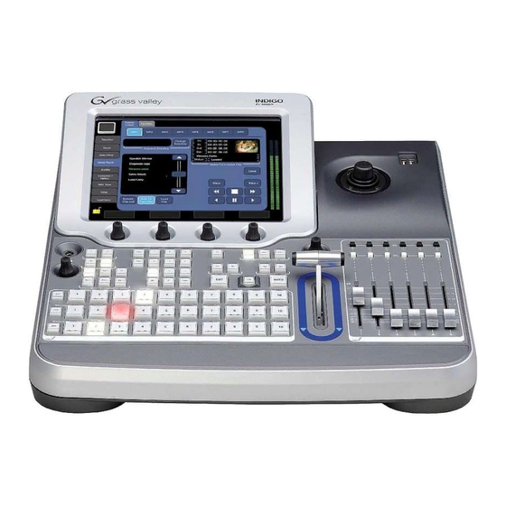
Section Technical Specifications Physical Dimensions All dimensions shown in millimeters. INDIGO AV MIXER Learn Key 1 Key 2 USER USER NEXT TRANSITION NEXT TRANSITION MASTER VOLUME MASTER VOLUME Shift Hi-Res DELEGATE DELEGATE Auto Auto Key 1 KEY 1 KEY 2 Key 2 KEY 1 KEY 2... -
Page 10: Physical Mounting
Section 2 — Technical Specifications Physical Mounting The Indigo AV Mixer is a single unit with no separate frame so no rack space is required. All connections mount directly to the back of the unit at the desk. Indigo is designed to sit on a desk and does not require a hole cut into a desk top. -
Page 11: Preliminary Specifications
Preliminary Specifications Preliminary Specifications Video Standards • NTSC/PAL: 50/59.94 Hz • HD-SDI: SMPTE 292M (720p or 1080i) • SD-SDI: SMPTE 272M (525 lines/625 lines) 8-bit • Composite: (525 lines/625 lines) 8-bit • DVI-I: • 640x480 up to 1280x1024 @ 60 Hz/75 Hz Video Input Connectors •... -
Page 12: Analog Audio Input Connectors
Section 2 — Technical Specifications • 3 composite (BNC) • 3 SD-SDI (BNC) Analog Audio Input Connectors • 2 stereo RCA pair (unbalanced) • 6 TRS analog stereo (balanced) • 4 XLR analog mono (balanced) (microphone) Analog Audio Output Connectors Main •... -
Page 13: Control And Interface
Technical Specifications Control and Interface • 2 Ref Sync out (BNC) • 1 Ref Sync loop in/out (BNC) • 2 RS-422 (9-pin D-sub) • 1 GPI I/O /TALLY (50-pin D-sub) • 2 USB (Standard-A) front panel • 1 100Base-T Ethernet Technical Specifications Power Supply •... - Page 14 Section 2 — Technical Specifications INDIGO AV MIXER — Installation & Planning Guide...
-
Page 15: Section 3 - Cabling
Section Cabling SDI / COMP S-VIDEO SDI / COMP S-VIDEO SDI / COMP COMP S-VIDEO COMP COMP COMP COMP AC POWER IN g r a s s va lle y TYPE INDIGO / RC 4100 PART NO. 0 219 410 010 SER. - Page 16 Section 3 — Cabling INDIGO AV MIXER — Installation & Planning Guide...
-
Page 17: Section 4 - Functional Overview
Section Functional Overview The Indigo AV Mixer combines characteristics of a number of devices and then scales and synchronizes the various inputs for an integrated presenta- tion. The SD video section includes external input connections for SD-SDI, Com- posite, S-Video and DV-25. The SD section also has access to internal sources scaled down from Hi-res as well as still stores and a color matte. -
Page 18: Sd Signal View
Section 4 — Functional Overview SD Signal View A total of 12 SD sources may be assigned to buttons from the available inputs. Keys may be either self (video) keyed or separate inputs for key and fill. Stills may be captured from incoming video or downloaded via USB in JPG, PNG or TGA file formats. -
Page 19: Hi-Resolution Video Signal Flow
Hi-Resolution Video Signal Flow Hi-Resolution Video Signal Flow A total of three Hi-resolution sources may be assigned to buttons from the available inputs. Two of the sources may be selected from either the external inputs or internal inputs and the third source is always upscaled from an SD source (may be a single source or the entire PGM mix). -
Page 20: Audio Signal Flow
Section 4 — Functional Overview Audio Signal Flow All inputs shown below are stereo. Any input may be assigned to any fader using the internal menus. Although there are only six faders, control for all inputs can be accessed through the touchscreen menu. The two inputs not assigned to faders may still be used for Audio Follow Video (AFV). -
Page 21: Aes/Ebu Pin Out
AES/EBU Pin Out AES/EBU Pin Out Digital audio I/O are available over SD-SDI, DV25, or AES/EBU. The pin out for the AES/EBU connector is shown below. AES/EBU DSUB 25 pins female 2x Digital Output, 6x Digital Input Figure 8. AES/EBU Pin Out Digital Audio Input Description IN1+... - Page 22 Section 4 — Functional Overview INDIGO AV MIXER — Installation & Planning Guide...
-
Page 23: Section 5 - External Device Control
Section External Device Control Control Signal Flow Reference signal is analog blackburst only. Editor control is achieved through GVG 100/200 protocol. Device control is achieved through AMP or BVW75 protocol. USB-B connection is not used on the device in its current release. Analog Reference CAT5 network 8 GPI inputs... -
Page 24: Gpo/Gpi I/O, Tally Pin Out
Section 5 — External Device Control GPO/GPI I/O, Tally Pin Out The following Indigo functions are currently available for external control through GPI inputs. • Turn audio channels on/off • Turn audio channels PFL • Recall timelines • Trigger Auto/Cut for any of the transition elements (or the complete GPI outputs can be set up for external device control or tally. - Page 25 Control Signal Flow Description GPO_12 GPO_13 GPO_14 GPO_15 GPO_16 Description GPI_1 GPI_2 GPI_3 GPI_4 GPI_5 GPI_6 GPI_7 GPI_8 The Indigo tally system has 16 universal relays that interface source tally and GPI Output information to an external system through the Tally Port connector.
-
Page 26: Turbo Connections
Section 5 — External Device Control Turbo Connections The recommended video connection between Turbo and Indigo is either SD-SDI or DVI-I. Audio may be connected via analog connectors or digi- tally from Turbo’s SPDIF output to Indigo’s AES-EBU input. Remote control of Indigo can be accomplished via RS422 or Ethernet connections. -
Page 27: Other Connections
Other Connections Other Connections Indigo’s DVI-I connector can be adapted for use with other sources by the use of commonly available adapter cables. Connection Type Requirement VGA computer DVI-I (or DVI-A male to VGA male adapter RGB video DVI-I (or DVI-A) male to 5 BNC INDIGO AV MIXER —... - Page 28 Section 5 — External Device Control INDIGO AV MIXER — Installation & Planning Guide...
-
Page 29: Section 6 - Replaceable Components
Section Replaceable Components Compact Flash Card Hi-Resolution Board Figure 11. Compact Flash Card and Hi-Resolution Board Location Hi-Resolution Card If the Indigo AV Mixer was ordered with the high-resolution (HR) inputs, the HR I/O card will arrive uninstalled. Remove both the base unit and HR input card from the box and place on an anti-static work surface. - Page 30 Section 6 — Replaceable Components Compact Flash The operating system software resides on a compact flash card which is inserted into Indigo as shown above. Under normal operating conditions, this card is never removed. Occasionally a software update may be required.
Need help?
Do you have a question about the Grass Valley INDIGO and is the answer not in the manual?
Questions and answers