
Summary of Contents for Miyachi Unitek LMV700
- Page 1 OPERATOR MANUAL 990-545 REVISION A January 2007 OPERATOR MANUAL FOR THE LMV700(E) LD PUMPED Nd:YVO AIR-COOLED LASER MARKER (Using LMDrawLite Marker Software)
-
Page 2: Revision Record
01/07 Release publication. CDRH COMPLIANCE STATEMENT The Miyachi Unitek Corporation LMV700(E) Nd:YVO Laser Marker is certified to be fully compliant with all applicable standards and regulations as set forth by the United States of America's Health and Human Services (HHS), Food and... -
Page 3: Table Of Contents
Safety Precautions ............................ vii Chapter 1: System Description Section I: Features ..........................1-1 Laser Marking ........................1-1 LMV700(E) ............................. 1-1 Section II: Part Names and Functions ....................1-3 Control Unit (Front) ........................1-3 Emergency Stop Button ......................1-3 Control Key Switch ........................1-4 Panel Indicators ........................ -
Page 4: Contents
Section III. Maintenance Procedures ....................4-5 User-serviceable Parts ......................4-5 Air Filter Inspection and Replacement ..................4-6 Control Unit Air Filter ......................4-6 Oscillator Air Filter ........................4-6 Clean and Replace Protective Glass ..................4-7 LMV700 Nd:YVO LASER MARKER 990-545... - Page 5 Replace the LD (Pumping Laser Diode) .................. 4-8 Lithium Battery Replacement ....................4-9 Repair Service .......................... 4-9 Appendix A: Technical Specifications ....................A-1 Appendix B: Electrical and Data Connections ..................B-1 Appendix C: Timing Diagrams ......................C-1 LMV700 Nd:YVO LASER MARKER 990-545...
-
Page 6: Contact Us
Phone: (626) 303-5676 FAX: (626) 358-8048 E-mail: info@miyachiunitek.com Miyachi Unitek Lasers is not responsible for any losses due to improper use of this product. About This Manual The contents of this manual are subject to change without notice. If you have any questions, find any errors/omissions, or if you have suggestions for improving this manual, please contact us. -
Page 7: Safety Precautions
Goggles having an optical density of at least 7 at a wavelength of 1064 nanometers for the operation of the LMV700(E) Marker. Appoint a Laser Safety Officer. The Laser Safety Officer (LSO) must provide personnel with sufficient training so that personnel can operate, maintain and service the Laser Marker safely. - Page 8 Refrain from any mechanical adjustment other, than maintenance specifically described in the operation manual. Never expose eyes or skin to laser irradiation. Exposure to direct or scattered laser light is extremely hazardous. Direct exposure of the eye to laser beams may result in blindness. LMV700 Nd:YVO LASER MARKER viii 990-545...
- Page 9 People using pacemakers must NOT approach the Laser Marker. Unless a physician has consented, pacemaker users must not approach the Laser Marker in use, or even approach the working area. The Laser Marker generates electromagnetic fields that may affect pacemaker function. LMV700 Nd:YVO LASER MARKER 990-545...
- Page 10 Keep a fire extinguisher nearby. Keep a fire extinguisher in the marking area in case of fire. Maintain and inspect the unit at periodic intervals. Maintain and inspect the unit at periodic intervals. Repair any damage before resuming use. LMV700 Nd:YVO LASER MARKER 990-545...
- Page 11 Attempting to operate several at a time may damage the Marker. 10. Do not turn the main switch for the Control Unit OFF while a computer is connected to the Control Unit. Instead power down the computer first, followed by the Control Unit. LMV700 Nd:YVO LASER MARKER 990-545...
- Page 12 Always wear protective goggles when maintaining the Marker. Goggles must have an optical density of at least 7+, at a wavelength of 1064 nanometers for the operation of the LMV700(E) Markers. 12. For more consistent marking, allow the unit to thermally stabilize for approximately 10 to 30 minutes before use.
-
Page 13: Chapter 1: System Description
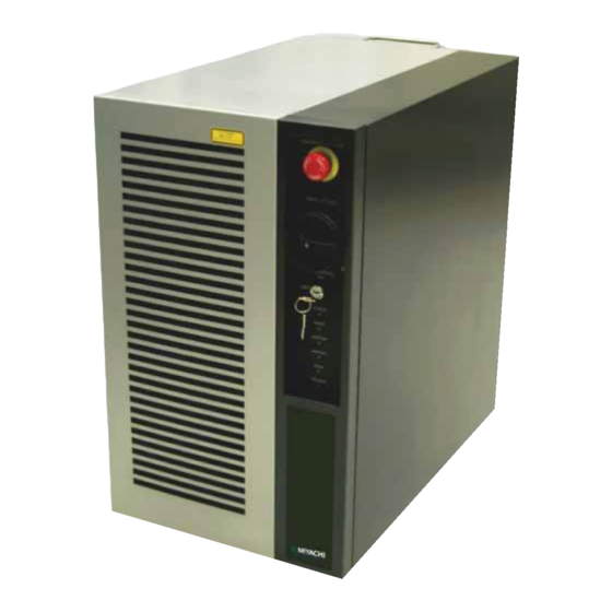
The LMV700(E) is a scanning laser diode (LD) pumped YVO laser marker. For the rest of this manual, the LMV700(E) Air-Cooled Laser Marker will simply be called the Marker. This Marker operates with LMDrawLite marker software. For the rest of the manual this software will simply be referred to as the software. - Page 14 Full-featured drawing functions allow more efficient production of marking data. Functions: move, rotate, copy, enlarge, reduce, compress, mirror text, reverse marking, undo, redo, grid, ruler. Auto backup Specify an interval (in time or number of operations) for automatic data backup. LMV700 Nd:YVO LASER MARKER 990-545...
-
Page 15: Section Ii: Part Names And Functions
Use this button to stop the device only in emergency situations. Frequent use of the emergency stop button will significantly affect the LD service life. Main Switch Turn to the ON position to supply power. Turn to the OFF position to cut the power supply and stop the unit. LMV700 Nd:YVO LASER MARKER 990-545... -
Page 16: Control Key Switch
Turn the main power switch OFF and check the voltage of the power source. Front Cover An air filter is located behind this cover. Clean the air filter at regular intervals. (Refer to Chapter 4: Maintenance for more details.) LMV700 Nd:YVO LASER MARKER 990-545... -
Page 17: Control Unit (Back)
Used for connecting the input power cable. Cooling Fans Used to cool the Control Unit. RF Connector Used to output the control signal for the Q-switch in the Oscillator Unit. Galvanoscanner Connector Used to output the control signals to the Galvanoscanner. LMV700 Nd:YVO LASER MARKER 990-545... -
Page 18: Oscillator Connector (D-Sub 25 Pin, Female)
Remove the cover and vacuum off any dust or dirt. (The appropriate cleaning interval will depend on the characteristics of the operating environment.) (Refer to Chapter 4: Maintenance for more details.) LMV700 Nd:YVO LASER MARKER 990-545... -
Page 19: Resonator Unit Cover
Mounting Brackets Used to secure the oscillator. Attach with the specified screws at four positions. LD (Laser Diode) Indicator Lamp Green when the LD is on. Shutter Indicator Lamp Yellow when the Safety Shutter is open. LMV700 Nd:YVO LASER MARKER 990-545... -
Page 20: Section Iii: System Configuration
Hard disk space 1 GB or more Computer Requirements (Must be ordered separately) Display resolution 1024 x 768 Interface Keyboard/mouse/USB 1.1 Operating system Windows XP (SP2 or later) USB cable 3 meters (Must be ordered separately) LMV700 Nd:YVO LASER MARKER 990-545... -
Page 21: Included Accessories
Peltier cooling device. When replacing an LD module, the graphite sheet must be free from cracks or damage. Lithium system battery CR2450 (Backup battery for internal memory.) USB cable For communications with a computer. LMV700 Nd:YVO LASER MARKER 990-545... -
Page 23: Chapter 2. Installation And Setup
Install the Oscillator with the f-theta lens facing downward. Make sure the radius of curvature of the optical fiber at the back of the Oscillator is at least 5.9” (15 cm). LMV700 Nd:YVO LASER MARKER 990-545... - Page 24 When moving the Oscillator, grab the carrying handles on both sides to avoid contact with the lens (see photograph). Do not hold the fiber or other cables. The oscillator weighs 20.9 lbs. (9.5kg). LMV700 Nd:YVO LASER MARKER 990-545...
-
Page 25: Section Ii: Installation
Insert the the power supply cable (6.5 feet (2m) maximum length) through the strain relief and cover. Connect the wires to the power supply terminals as defined below. LMV700 Nd:YVO LASER MARKER 990-545... - Page 26 Adjust the power cable as necessary then tighten the strain relief. 7. Connect to a single-phase power source of 100 to 240 VAC (+6%/-10%), 50/60 Hz (± 3%), 1kVA minimum. The Marker will automatically switch the input voltage. LMV700 Nd:YVO LASER MARKER 990-545...
-
Page 27: Connect The Signal Cables
CHAPTER 2: INSTALLATION AND SETUP Connect the Signal Cables Connect the interconnect cables between the Marker Control Unit, Marker Oscillator, and Computer. Connect all cables as shown below. Secure all cables by fastening the connector backshells. LMV700 Nd:YVO LASER MARKER 990-545... -
Page 28: Connect The Optical Fiber
Set the distance as shown on the right. If the marking quality is unacceptable, then slightly adjust the marking material towards and away from the lens until the marking quality is acceptable. LMV700 Nd:YVO LASER MARKER 990-545... -
Page 29: Section Iii: Software Installation And Set-Up
When Supplying your own Computer USB Driver Installation The LMV700 is controlled through a USB cable that is connected to your computer. To prevent installation problems, be sure to install the USB driver as outlined below. 1. Load the included CD-ROM into the computer. - Page 30 [ ] driver on MUM_0001 the CD-ROM, followed by Open 9. Once the driver is installed, the following screen will appear. Select ] to close the screen. Finish The USB driver is now installed. LMV700 Nd:YVO LASER MARKER 990-545...
-
Page 31: Lmdrawlite Installation
[Install Program] When the welcome window appears, select the button. [Next] Read the installation notes, then select radio button to indicate that [Agree] you agree to the terms and conditions, then select the button. [Next] LMV700 Nd:YVO LASER MARKER 990-545... - Page 32 7. After the Software is installed, the following window will appear. Select to close the window. [Finish] Select to close the [Exit] LMDraw/LMDrawLite Install CD window displayed in Step 1. The Software is now installed. LMV700 Nd:YVO LASER MARKER 2-10 990-545...
-
Page 33: Computer Environment Set-Up
From the Control Panel, choose the icon to view the Display [Display] properties. 5. Choose the tab and set [Screen Saver] the Screen Saver property to (None) followed by [OK] 6. Close the Control Panel. File > Close LMV700 Nd:YVO LASER MARKER 990-545 2-11... -
Page 35: Chapter 3. Operating Instructions Section I: Before You Start
7 , at a wavelength of 1064 nanometers for the operation of the LMV700(E) Marker. Never look directly into the laser beam. WARNING Never operate the Marker in any manner other than described in this manual. Doing so may expose personnel to laser radiation or electrical hazards. -
Page 36: Section Ii: Start-Up Operating Instructions
LD is warming up. 13. Once the status display turns green, the Marker is ready for operation. Starting Up Refer to the LMDrawLite Software Manual, 990-546 for instructions on how to use the LMDrawLite software. LMV700 Nd:YVO LASER MARKER 990-545... -
Page 37: Section Iii: Shutdown
6. Exit the LMDrawLite program by selecting File > Exit CAUTION Never disconnect the USB cable if the [Online] display is lit. Doing so may result in loss of data and prevent the unit from restarting. LMV700 Nd:YVO LASER MARKER 990-545... -
Page 39: Chapter 4. Maintenance
Keep the exterior of the Marker clean. Do not use paint thinner, benzene or acetone. Use a dry or slightly dampened cloth or, if heavily soiled, use a cloth moistened with a mild detergent or alcohol. LMV700 Nd:YVO LASER MARKER 990-545... -
Page 40: Section Ii: Troubleshooting
— Battery Voltage Drop Replace the battery. Reattach the cover if the oscillator or control unit cover Cover Open or Fiber Interlock circuit — is detached, or reconnect the fiber interlock connector opened (if disconnected). LMV700 Nd:YVO LASER MARKER 990-545... - Page 41 If the error persists after checking the RF cable connection and restarting, contact your Miyachi representative. An RF temperature error has occurred. RF Temperature Error If the error persists after restarting, contact your Miyachi representative. LMV700 Nd:YVO LASER MARKER 990-545...
- Page 42 — Out Of Memory: Layout Registration supported. Check layout file registration. — = No Change. In the event of errors other than those listed above, contact your Miyachi representative to identify the error code. LMV700 Nd:YVO LASER MARKER 990-545...
-
Page 43: Section Iii. Maintenance Procedures
Graphite sheet – 090-047 Replace replaced – L-05269-003 2 years Replace Repair at end of Refurbished L-05269-004 service life Protective eyewear (glasses) – 475-118 – Replace Protective eyewear (over the glasses) – 475-160 – Replace LMV700 Nd:YVO LASER MARKER 990-545... -
Page 44: Air Filter Inspection And Replacement
6. Re-attach the front cover to the Control Unit. Oscillator Air Filter Remove the air filter cover by pulling forward on the side finger tab. 2. Use a vacuum cleaner to remove dust from the filter. 3. Re-attach the cover to the Oscillator. LMV700 Nd:YVO LASER MARKER 990-545... -
Page 45: Clean And Replace Protective Glass
NOTE: If you can not get the protective glass clean after several attempts, replace the protective glass with a new unit. Install the protective glass back onto the Marker by turning it in the CW (clockwise) direction. LMV700 Nd:YVO LASER MARKER 990-545... -
Page 46: Ld (Laser Diode) Inspection And Replacement
Before replacing the LD (Laser Diode) Module, turn the power to the equipment OFF and wait for at least five minutes before starting work. If you start the work with the power turned ON, electric shock, fire, or personal injury (burns, blindness, etc.) may occur. LMV700 Nd:YVO LASER MARKER 990-545... - Page 47 Phillips Screwdriver (cover screws) 8mm open-ended wrench 1. Remove the six Phillips-head screws on the back of the Control Unit. Slide the side covers backwards approximately ½” 1”, then lift the covers upward to remove. LMV700 Nd:YVO LASER MARKER 990-545...
- Page 48 LD Module. 4. Disconnect the thermal switch relay connector (located on the left side of the Marker). Disconnect the LD protection relay, Peltier power supply and LD Power Supply connectors. LMV700 Nd:YVO LASER MARKER 4-10 990-545...
- Page 49 Turn the fastening nut of the optical fiber CCW (counter-clockwise) with an 8mm wrench. Slowly pull out the optical fiber. 9. Immediately place a dust-proof cap on the fiber to prevent dust from collecting on the fiber end face. LMV700 Nd:YVO LASER MARKER 990-545 4-11...
- Page 50 18. Move the short circuit jumper to the terminals on the LD module before powering up the Laser Marker. Failure to remove the short circuit between the Red and Black terminals may damage the LD Module. LMV700 Nd:YVO LASER MARKER 4-12 990-545...
- Page 51 For more information, refer to the LD Module documentation and the 990-546, LMDrawLite Operators Manual. NOTE: For a fee, used LDs can be reconditioned to their original performance levels. For more information, please contact your Miyachi representative. LMV700 Nd:YVO LASER MARKER 990-545 4-13...
-
Page 52: Lithium Battery Replacement
7. Replace the Side Cover. Repair Service If you have problems with your Marker that you cannot resolve, please contact the Miyachi Unitek Corporation at the address, phone number, or e-mail address indicated in the front of this manual. LMV700 Nd:YVO... -
Page 53: Appendix A: Technical Specifications
0.5 G max. Oil mist, dust 0.1 mg/m max. DIN, JIS Z 8905, JIS Z 8904, JIS Z 8903, OCR- Typefaces A, OCR-B, and Roundhand font Marking Letters (uppercase and lowercase), numbers, and Supported characters symbols LMV700 Nd:YVO LASER MARKER 990-545... - Page 54 160 (fixed) Scanning method Galvanometer scanner Marking Area Square Marking area 3.94” × 3.94” (100 mm x 100 mm) Working distance 6.50 in. (165 mm) Position resolution 2 μm Marking speed 0.01 to 11,000 mm/s LMV700 Nd:YVO LASER MARKER 990-545...
- Page 55 APPENDIX A: TECHNICAL SPECIFICATIONS Section II. Dimensions Control Unit LMV700 Nd:YVO LASER MARKER 990-545...
- Page 56 APPENDIX A: TECHNICAL SPECIFICATIONS Marking Head LMV700 Nd:YVO LASER MARKER 990-545...
-
Page 57: Appendix B: Electrical And Data Connections
*1 This signal is valid when the mode is set to “Remote”. Signal is invalid when mode is set to “Local”. *2 Stops all serial counters. *3 The signals for the individual counters can be enabled or disabled. LMV700 Nd:YVO LASER MARKER 990-545... - Page 58 When the Count up serial counter is reset (to either the minimum or maximum value), the output signal will toggle *1 Marking standby is during the marking process or when writing data to the internal memory. LMV700 Nd:YVO LASER MARKER 990-545...
- Page 59 APPENDIX B: ELECTRICAL AND DATA CONNECTIONS When Connected to a 24 VDC Source Output PLC LMV700 Nd:YVO LASER MARKER 990-545...
- Page 60 APPENDIX B: ELECTRICAL AND DATA CONNECTIONS When Using Contact Signals LMV700 Nd:YVO LASER MARKER 990-545...
- Page 61 APPENDIX B: ELECTRICAL AND DATA CONNECTIONS When Using Open Collector Signals LMV700 Nd:YVO LASER MARKER 990-545...
- Page 62 NOTE: Be sure to use a connecting cable with a shield line and terminate the shield line appropriately. Interlock INPUT Signal When the Interlock input signal is turned (opened), the Main (safety) Shutter in the Oscillator will close, preventing marking. However, the LD will remain Timing Diagram LMV700 Nd:YVO LASER MARKER 990-545...
-
Page 63: Appendix Ctiming Diagrams
The ‘Marking start input’ should be toggled only when ‘Marking standby output’ and “Remote mode output’ are When the ‘Remote mode output’ is (Local mode), the ‘Marking start input’ is disabled. The Remote Mode (Remote/Local) can also be set from the PC. LMV700 Nd:YVO LASER MARKER 990-545... - Page 64 . When laser trouble occurs the ‘Standby output’, ‘LD illuminated output’ and ‘Marking-in-progress outputs’ will turn When the operator clears the error and toggles the ‘Error reset input’, the ‘LD illuminated output’ and ‘Marking standby output’ will turn back LMV700 Nd:YVO LASER MARKER 990-545...
- Page 65 APPENDIX C: TIMING DIAGRAMS When A Data Error Occurs When Marking is Stopped When the ‘Marking stop input’ signal is toggled, the marking process stops. This signal is typically used whenever the ‘Marking-in-progress’ output is turned LMV700 Nd:YVO LASER MARKER 990-545...
- Page 66 ‘Standby output’ will toggle during the LD cooling cycle. The ‘Standby output’ will toggle back once the LD is cool, indicating that it is safe to turn the main power switch. LMV700 Nd:YVO LASER MARKER 990-545...
- Page 67 CAUTION Marking stops once the counter end value has been marked. Depending on the layout marking sequence, some marking data may not be marked. Therefore the data that is being counted, should be marked last. LMV700 Nd:YVO LASER MARKER 990-545...
- Page 68 *15 The counter value increases or decreases during the marking process. CAUTION If a number of counters are used with the same conditions for a single layout, the counter value may not always be the same when marking halts during marking. LMV700 Nd:YVO LASER MARKER 990-545...
- Page 69 Lens .............. 1-7 Components ............1-8 Computer Environment Set-up ......2-11 Features .............. 1-1 Connect the Optical Fiber ........2-6 LMV700(E) ............ 1-1 Connect the Power Cable ........2-3 Laser Marking ........1-1 Connect the Signal Cables .......2-5 Fiber Guard Shaft ..........1-5 Connection Diagram ..........1-8...
- Page 70 Optical Fiber Fixture ........... 1-5 Lithium Battery Replacement .......4-9 Options .............. 1-9 LMDrawLite Installation ........2-9 Oscillator (Side) ..........1-6 LMV700(E) ............1-1 Exhaust Fan ............ 1-7 f Lens ............1-7 Fiber Interlock ..........1-6 Intake Fan ............1-6 Resonator Unit Cover ........1-7 Maintenance ............4-1...
- Page 71 Components ............ 1-8 System Configuration ...........1-8 Connection Diagram ........1-8 System Description ..........1-1 Features ............1-1 Included Accessories ........1-9 LMV700(E) ..........1-1 Options ..............1-9 Laser Marking .........1-1 Part Names and Functions .......1-3 Control Unit (Back) ........1-5 Circuit Breaker ...........1-5 Technical Specifications ........A-1 Cooling Fans ..........1-5...
Need help?
Do you have a question about the LMV700 and is the answer not in the manual?
Questions and answers