Advertisement
Quick Links
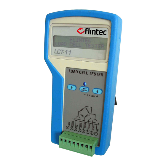
LCT-11 Quick User Guide
1. Before the instrument can be used for the first time you have to insert 4
batteries of type AA. The battery box can be accessed from the rear side of
the instrument after the protective cover has been removed. After the
batteries have been inserted you can refit the protective cover.
2. The Instrument is off. If this is not the case please turn off the instrument by
pressing the <On/Off> key for approx. 5 seconds.
3. Connect the wires of the oad cell cable to the correct pins of the input
connector, but make sure that the SCREEN and the BODY are NOT
connected.
4. Power on the instrument by pressing the <On/Off> key for approx. 2
seconds.
5. The display will show the "Welcome" screen for a few seconds. Then it will
ask for the load cell connection type: 4-wire OR 6-wire.
6. For the best accuracy of the high resistance measurements (leakage) it's
now a good opportunity to run a calibration. Press the <↓> and the
<On/Off> key simultaneously. The display will show "Calibrating"...and after
2 seconds the instrument is calibrated.
7. Now connect the SCREEN and the BODY (of the load cell) to the input
connector.
8. Select your load cell connection type (4-wire or 6-wire) and press <Enter>.
9. Select the rated output of the load cell with the <↑> and <↓> keys and press <Enter>.
10. Press the <Enter> button for a full load cell test cycle OR press the <↓> key for the continuous display
mode (GAIN).
If the Full load cell test cycle was selected:
The LCD will display "Test in progress" and the LED will flash for a few seconds. Once the test cycle is
finished you may scroll the results by pressing the <↑> key.
The results will be displayed in the following sequence:
Input
Output
Sense+
Sense-
Signal output
Shield to bridge
Body to bridge
Shield to body
LCT-11 Quick User Guide Rev.1.1.0, November 2020
Resistance between Ex+ and Ex- (Max. 5000 ohm)
Resistance between Signal+ and Signal- (Max. 5000 ohm)
Resistance between Ex+ and Sense+ (Max. 500 ohm; valid for 6-wire cables only)
Resistance between Ex- and Sense- (Max. 500 ohm; valid for 6-wire cables only)
Load cell signal in percentage of full load cell capacity
Note: In case of a broken cable or a very high input/output resistance the display
will show "Can not measure"
Insulation resistance between the cable shield (screen) and the bridge
Insulation resistance between the load cell body and the bridge
Resistance between the cable shield (screen) and the load cell body
Page 1 of 3
Advertisement

Summary of Contents for Flintec LCT-11
- Page 1 Shield to bridge Insulation resistance between the load cell body and the bridge Body to bridge Resistance between the cable shield (screen) and the load cell body Shield to body LCT-11 Quick User Guide Rev.1.1.0, November 2020 Page 1 of 3...
- Page 2 The LCT-11 is the only measuring tool required to perform the tests either on site or in the lab. Before you start, make sure to have the load cell specifications and the cable colour code available (usually you get the information with the load cell, or you can find it on the internet: see www.flintec.com).
- Page 3 Please note that if the device is not used for a longer period (we recommend 3 days), the batteries must be removed from the LCT-11. If the batteries leak, they may damage the device LCT-11 Quick User Guide Rev.1.1.0, November 2020...