
Summary of Contents for Emakefun RF-NANO
- Page 1 RF-NANO Operating Instruction V.1.0 Copy right © 2018 Shenzhen Emakefun Technology co., Ltd.
- Page 2 Revision history Date Version Description Author V.1.0 Create a document Abbott.Chen 2019-7-25 Copy right © 2018 Shenzhen Emakefun Technology co., Ltd.
-
Page 3: Table Of Contents
3.3.2 program code .......................... 29 Chapter 4 Sets the transmitting power and data transmission rate ..............33 4.1 Set the transmitted power of RF-NANO ................... 33 4.2 Set RF-NANO data transfer rate ......................34 Copy right © 2018 Shenzhen Emakefun Technology co., Ltd. -
Page 4: Chapter 1 Rf-Nano Introduce
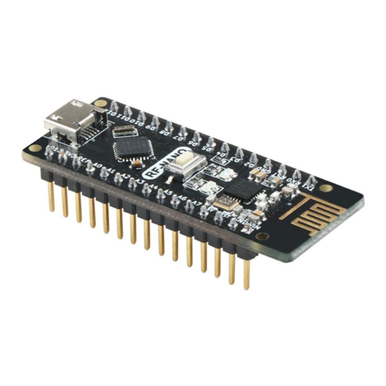
NANO board and an NRF24L01+ module into one, as shown in figure 1-1-1. It is more convenient to use, and the small size rf-nano is exactly the same as the common pin of NANO board, convenient for transplantation. - Page 5 Figure 1-1-2 Copy right © 2018 Shenzhen Emakefun Technology co., Ltd.
-
Page 6: Rf-Nano Mcu Introduce
Figure 1-1-3 1.2 RF-NANO MCU introduce Arduino rf-nano MCU is ATmega328(Nano3.0), usb-micro interface, with 14 channels of digital input/output (6 channels can be used as PWM output), 8 channels of analog input, a 16MHz crystal oscillator, a usb-micro port, an ICSP header and a reset button. -
Page 7: Power Supply
Reset:The microcontroller chip is reset when the signal is low. 1.2.4 Communication Interface Serial port: The built-in UART of ATmega328 can communicate with external serial port through digital port 0 (RX) and 1 (TX). Copy right © 2018 Shenzhen Emakefun Technology co., Ltd. -
Page 8: Atmega328 With Nrf24L01+ Of Communication
ATmega328 and NRF24L01+ are SPI communication, and the schematic diagram is shown in figure 1-2-1; Figure 1-2-1 ATmega328 and NRF24L01+ chip pin connection: ATmega328 NRF24L01+ +3.3V MOSI MISO Note :ATmega328 already occupied pins D9,D10,D11,D12, and D13 cannot be reused Copy right © 2018 Shenzhen Emakefun Technology co., Ltd. -
Page 9: Downloader
Everyone can download according to their own computer system, of course, There will be a downloaded installation package on our companion CD, but only the Windows version, because this tutorial is all running under Windows system. Copy right © 2018 Shenzhen Emakefun Technology co., Ltd. - Page 10 IDE. After the installation is complete, click "arduino.exe" again to enter the IDE programming interface. Figure 1-3-2 ArduinoIDE installation package Copy right © 2018 Shenzhen Emakefun Technology co., Ltd.
- Page 11 Then we open the IDE, select the corresponding development board model and port in the toolbar and it will work normally. If it appears as shown in figure 1-3-5, it shows that the computer does not recognize the development board and needs to install the driver itself Copy right © 2018 Shenzhen Emakefun Technology co., Ltd.
-
Page 12: Driver Installation
1)Right-click "my computer" (open device manager (look at ports (COM and LPT).At this point you will see a "USB serial port", right-click "USB serial port" and select the "update driver software" option. Copy right © 2018 Shenzhen Emakefun Technology co., Ltd. - Page 13 Figure 1-3-7 3) Finally, select the driver file named CH341SER_for_64bit_win7, which is located in the Arduino_Nano board driver folder. Please select the corresponding driver version according to your computer system model Figure1-3-8 Copy right © 2018 Shenzhen Emakefun Technology co., Ltd.
- Page 14 At this point, we can go back to the device manager interface and see that the computer has successfully recognized Arduino. As shown in figure 1-3-11 below, open the Arduino compilation environment and start the Arduino journey Copy right © 2018 Shenzhen Emakefun Technology co., Ltd.
- Page 15 10) once the system starts, you can install the Arduino driver as with Windows7 Copy right © 2018 Shenzhen Emakefun Technology co., Ltd.
-
Page 16: Chapter 2 Working Principle Of Rf-Nano
CE decreases, NRF24L01+ enters idle mode 1.Always go into standby or power down mode before writing registers.As shown in figure 2-1-1, SPI operation sequence diagram is given: Copy right © 2018 Shenzhen Emakefun Technology co., Ltd. -
Page 17: Config Word
SPI mouth NRF24L01 +Of the 25 configuration registers, the most common configuration registers are shown in table Table 2: common configuration registers Register name Function Addres s(H) Copy right © 2018 Shenzhen Emakefun Technology co., Ltd. -
Page 18: Rf-Nano Work Module
NRF24L01+ there is a state machine inside the chip, which controls the conversion between different working modes of the chip. NRF24L01+ can be configured as Shutdown、 Standby、 Idle-TX、 TX and RX Five working modes.The state transition diagram is shown in figure 2-3-1. Copy right © 2018 Shenzhen Emakefun Technology co., Ltd. -
Page 19: Chapter3 Realizes The Communication Between Rf-Nano
Chapter3 realizes the communication between rf-nano 3.1 Implement two rf-nano point-to-point communication 3.1.1 connect method Prepare two rf-nano or an rf-nano and NRF24L01+ module, and an Arduino UNO R3(Arduino NANO V3.0), as shown in figure 3-1-1. Transmitting device Receiving device 2.4G... -
Page 20: Principle Of Application
1、Firstly, configure the nRF24L01 to transmit mode. 2、Then write the address TX_ADDR of the receiving end and the data TX_PLD to be sent into the nRF24L01 buffer area by the SPI port in time sequence. Copy right © 2018 Shenzhen Emakefun Technology co., Ltd. -
Page 21: Program Code
Code path: RF-NANO Demo Program\Peer-to-peer Communication\Emitter\Emitter.ino Code source //Transmitter program #include <SPI.h> #include "Mirf.h" #include "nRF24L01.h" #include "MirfHardwareSpiDriver.h" Nrf24l Mirf = Nrf24l(10, 9); value; String vas; void setup() Serial.begin(9600); Copy right © 2018 Shenzhen Emakefun Technology co., Ltd. - Page 22 //Set the receiver address value 32765;//random(255); //0-255 random number Mirf.send((byte *)"A"); //Send instructions, send random number value Serial.print("Wait for sending.."); while (Mirf.isSending()) delay(1); //Until you send successfully, exit the loop Serial.print("Send success:"); Serial.println(value); delay(1000); Copy right © 2018 Shenzhen Emakefun Technology co., Ltd.
- Page 23 #include <SPI.h> #include "Mirf.h" #include "nRF24L01.h" #include "MirfHardwareSpiDriver.h" Nrf24l Mirf = Nrf24l(10, 9); value; //String void setup() Serial.begin(9600); Mirf.spi = &MirfHardwareSpi; Mirf.init(); Mirf.setRADDR((byte *)"FGHIJ"); //Set your own address (receiver address) using Copy right © 2018 Shenzhen Emakefun Technology co., Ltd.
-
Page 24: Implement Multiple Send To A Receive Communication
Mirf.getData((byte *) &value); Serial.print("Got data: "); Serial.println(value); Data received by a receiving device Figure 3-1-2 3.2 Implement multiple send to a receive communication 3.2.1 Experimental principle block diagram Copy right © 2018 Shenzhen Emakefun Technology co., Ltd. -
Page 25: Program Code
(RF-NANO) Receiving device (RF-NANO) Transmitting device 2 (RF-NANO) 3.2.2 program code Transmitting data program 1 code: Code path:RF-NANO Demo Program\Multiple send to one receive communication\Emitter1 \Emitter1.ino Source code #include <SPI.h> #include "Mirf.h" #include "nRF24L01.h" #include "MirfHardwareSpiDriver.h" Nrf24l Mirf = Nrf24l(10, 9);... - Page 26 Serial.println(value); delay(1000); Data sent by transmitter 1: Figure 3-2-1 Launch data program 2 code: Code path: RF-NANO Demo Program\Multiple send to one receive communication\Emitter2\Emitter2.ino Source code //Transmitter program Copy right © 2018 Shenzhen Emakefun Technology co., Ltd.
- Page 27 = 200; //0-255 random number Mirf.send((byte *)&value); //Send instructions, send random number value Serial.print("Wait for sending.."); while (Mirf.isSending()) delay(1); //Until you send successfully, exit the loop Serial.print("Send success:"); Serial.println(value); delay(1000); Copy right © 2018 Shenzhen Emakefun Technology co., Ltd.
- Page 28 Data sent by transmitter 2: Figure 3-2-2 Receiving data program code: Code path: RF-NANO Demo Program\Multiple send to one receive communication \All_Receive\ All_Receive.ino Source code Data received by a receiving device: Figure 3-2-3 Copy right © 2018 Shenzhen Emakefun Technology co., Ltd.
-
Page 29: Implement A Send To Multiple Receive Communication
(RF-NANO) Transmitting devcie (RF-NANO) Receiving device 2 (RF-NANO) 3.3.2 program code Transmit data program code: Code path: RF-NANO Demo Program\One send to multiple receive communication\All_Emitter \All_Emitter.ino Source code //Transmitter program #include <SPI.h> #include "Mirf.h" #include "nRF24L01.h" #include "MirfHardwareSpiDriver.h"... - Page 30 //Set the receiver address value2 = 200; Mirf.send((byte *)&value2); //Send instructions, send random number value Serial.print("Wait for sending.."); while (Mirf.isSending()) delay(1); //Until you send successfully, exit the loop Serial.print("value2 Send success:"); Serial.println(value2); delay(500); Copy right © 2018 Shenzhen Emakefun Technology co., Ltd.
- Page 31 Data sent by transmitter: Figure 3-3-1 Receiving data program code 1: Code path:RF-NANO Demo Program\One send to multiple receive communication\ Receive1\Receive1.ino Source code //Receiver program #include <SPI.h> #include "Mirf.h" #include "nRF24L01.h" #include "MirfHardwareSpiDriver.h" Nrf24l Mirf = Nrf24l(10, 9);...
- Page 32 //When the program is received, the received data is output from the serial port Mirf.getData((byte *) &value); Serial.print("Receive1 got data is: "); Serial.println(value); delay(800); Data received by receiving device 1: Figure 3-3-2 Copy right © 2018 Shenzhen Emakefun Technology co., Ltd.
-
Page 33: Chapter 4 Sets The Transmitting Power And Data Transmission Rate
Open the rf-nano experimental routine program. In mirf. CPP, there is a function to set the transmitted power :SetOutputRF_PWR(uint8_t val), which can set different transmitted power... -
Page 34: Set Rf-Nano Data Transfer Rate
RF-NANO data transmission rate has three levels, namely :1Mbps, 2Mbps, 250Kbps;Data transmission rate can be set in the software. Open the rf-nano experimental routine program. In mirf. CPP, there is a function to set the data transmission rate :SetSpeedDataRates(uint8_t val)。...
Need help?
Do you have a question about the RF-NANO and is the answer not in the manual?
Questions and answers