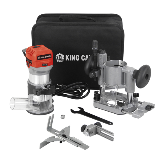
Summary of Contents for King Canada 8366K
- Page 1 VARIABLE SPEED ROUTER/TRIMMER COMBO KIT MODEL: 8366K INSTRUCTION MANUAL COPYRIGHT © 2020 ALL RIGHTS RESERVED BY KING CANADA TOOLS INC.
-
Page 2: Warranty Information
Contact your retailer or visit our web site at www.kingcanada.com for an updated listing of our authorized service centers. In cooperation with our authorized service centre, King Canada will either repair or replace the product if any part or parts covered under this warranty which examination proves to be defective in workmanship or material during the warranty period. - Page 3 GENERAL & SPECIFIC SAFETY INSTRUCTIONS 1. KNOW YOUR TOOL Read and understand the instruction manual and labels affixed to the tool. Learn its application and limitations as well as its specific potential hazards. 2. Don’t use power tools in damp or wet locations or expose them to rain. Keep work area well lit and provide adequate surrounding work space.
-
Page 4: Electrical Information
ELECTRICAL INFORMATION WARNING: The warnings, cautions, and instructions discussed in this instruction manual cannot cover all possible conditions and situations that may occur. It must be understood by the operator that common sense and caution are factors which cannot be built into this product, but must be supplied by the operator. -
Page 5: Getting To Know Your Tool
16. Fixed base 8. Collet nut adjustment wrench 17. On/Off switch 9. Roller guide 10. 3 preset depth stops SPECIFICATIONS Model ........................8366K Motor/Amperage ..................1-1/4 HP/6.5A Voltage........................120V Cycle/Phase ....................60Hz, 1 phase RPM ......................10,000 - 32,000 Collet capacity....................1/4” & 3/8” Insulation class ......................Double... - Page 6 ASSEMBLY Installing or Removing Bits Caution: Make sure the tool is switched off and unplugged before installing or removing a bit. This Router/Trimmer kit comes with 2 collets (1/4” and 3/8”), this means 1/4” and 3/8” shank bits can be installed on this tool. If you desire to use a 1/4”...
- Page 7 ADJUSTMENTS & OPERATION Adjusting Depth of Cut To adjust the protrusion of the installed bit (depth of cut), release the locking lever (A) Fig.4 and turn the adjustment knob (B) to move the body up or down. Now adjust the fixed base position until you reach your desired protrusion of the installed bit (depth of cut) past the bottom of the fixed base.
- Page 8 ADJUSTMENTS & OPERATION Operational Guidelines Set the tool base on the workpiece to be cut without the bit making any contact. Then turn the tool on and wait until the bit reaches full speed. Move the tool forward over the workpiece surface, keeping the tool base flush and advancing smoothly until the cutting is complete.
- Page 9 ADJUSTMENTS & OPERATION Circular Cutting Circular cutting may be accomplished if you assemble the straight guide and guide plate as shown in Fig 10. (Min. 2-3/4” to 4-3/4”, Max. 4-3/4” to 8-11/16”). Minimum radius is 2-3/4” and maximum radius is 8-11/16”. Note: Circles between 6-3/4”...
- Page 10 Installing Plunge Base/Using as a Router continued... Place the tool on a flat surface. Loosen the plunge base lock lever (A) Fig.13 and lower the tool body until the bit just touches the flat surface. Tighten the plunge base lock lever to lock the tool body.
- Page 11 (included). Install new carbon brushes and reinstall the carbon brush caps. PARTS DIAGRAM & PARTS LISTS Refer to the Parts section of the King Canada web site for the most updated parts diagram and Figure 15 parts list.


Need help?
Do you have a question about the 8366K and is the answer not in the manual?
Questions and answers