
Subscribe to Our Youtube Channel
Summary of Contents for Federal Signal Corporation Pathfinder PF100
- Page 1 Pathfinder ® Installation and Maintenance Instructions 25500463 C1 1120 Printed in U.S.A. © Copyright 2018-2020 Federal Signal Corporation...
- Page 2 A copy of this limited warranty can also be obtained by written request to Federal Signal Corporation, 2645 Federal Signal Drive, University Park, IL 60484, email to info@fedsig.com or call +1 708-534-3400.
-
Page 3: Table Of Contents
Contents Safety Messages for Installers and Operators ................5 Safety Messages to Installers of Sound/Light Systems .................. 5 Safety Messages to Operators of Sound/Light Systems .................8 An Overview of the Pathfinder ® ..............................10 Siren, PA, and Speakers ............................10 Light Bars and SignalMaster Control .........................10 ®... - Page 4 Safety Messages ..........................32 Safety Messages to Personnel Servicing Federal Electronic Sirens ............32 Servicing the Pathfinder ........................33 Replacing the Slide Switch ..........................33 Getting Technical Support and Service ..................35 Getting Repair Service ............................35 Tables Table 1 System Specifications ............................ 11 Table 2 Siren Specifications ............................
-
Page 5: Safety Messages For Installers And Operators
Safety Messages for Installers and Operators Safety Messages for Installers and Operators For your safety, read and understand this manual thoroughly before installing, operating, and servicing the Pathfinder siren amplifier/relay module. The safety messages presented in this chapter and throughout the manual are reminders to exercise extreme care at all times. - Page 6 Safety Messages for Installers and Operators During Installation • Do NOT get metal shavings inside the product. Metal shavings in the product can cause the system to fail. If drilling must be done near the unit, place an ESD-approved cover over the unit to prevent metal shavings from entering the unit.
- Page 7 Safety Messages for Installers and Operators • Locate the control head so the vehicle, controls, and microphone can be operated safely. • When drilling into a vehicle structure, ensure that both sides of the surface are clear of anything that could be damaged. All drilled holes should be deburred and all sharp edges should be smoothed.
-
Page 8: Safety Messages To Operators Of Sound/Light Systems
Safety Messages for Installers and Operators Safety Messages to Operators of Sound/Light Systems People’s lives depend on your safe operation of Federal Signal products. It is important to read and follow all instructions shipped with the products. Listed below are some other important safety instructions and precautions you should follow: •... - Page 9 Safety Messages for Installers and Operators mounting surface. An improperly secured light could fall off of the vehicle, causing injury and damage. • The holding power of magnetic mounting systems is dependent upon surface finish, surface flatness, and thickness of the steel mounting surface. Therefore, to promote proper magnetic mounting: •...
-
Page 10: An Overview Of The Pathfinder
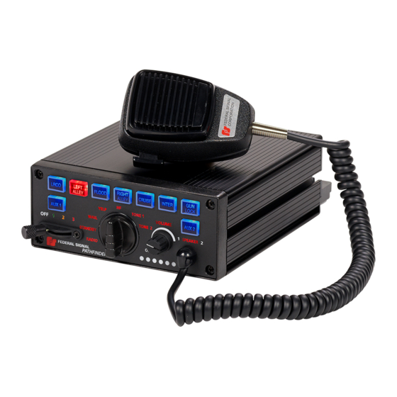
An Overview of the Pathfinder® An Overview of the Pathfinder ® The Pathfinder siren is a full-featured, programmable, electronic siren and light control system. State-of-the-art microprocessor technology is used to create a system with a small, compact siren system that can be installed under the dashboard (Self -Contained), in the trunk, or under the seat (remote) of any vehicle with a 12 V or 24 V negative ground system. -
Page 11: Fs Vehicle Integration
An Overview of the Pathfinder® FS Vehicle Integration The Pathfinder ® siren includes the capability to integrate with the existing vehicle CAN bus. The FS Vehicle Integration uses a vehicle-specific cable (not included) to seamlessly integrate with the vehicle. Vehicle events can be programmed with the Convergence Network Configuration Software to interface with the lighting/siren control. -
Page 12: Siren Specifications
An Overview of the Pathfinder® Siren Specifications Table 2 Siren Specifications Speakers One or two 100 W, 11-ohm speakers or One 100 W, 11-ohm speaker and two Rumbler speakers Operating Current 100 W - One 11-ohm speaker – 8 A 200 W - Two 11-ohm speakers –... -
Page 13: Pathfinder Kit Contents
An Overview of the Pathfinder® Pathfinder Kit Contents Tables 4 through 6 list the parts included with the kit. After unpacking the kit, examine it for damage that may have occurred in transit. If the product has been damaged, file a claim immediately with the carrier stating the extent of damage. Carefully check all envelopes, shipping labels, and tags before removing or destroying them. -
Page 14: Table 5 Pf100R And Pf200R Kit Contents
An Overview of the Pathfinder® Table 5 PF100R and PF200R Kit Contents Qty. Description Part Number - Part Number - PF100R PF200R 100 or 100/200-Watt Amplifier, Pathfinder 862302662-100 862302662 Control Head, Remote, PF200R, Pathfinder 862302151 862302151 Keypad Legend Stickers 8572294 8572294 Dynamic Microphone with Mod 258B577-03... -
Page 15: Table 6 Pf200-Rm Kit Contents
An Overview of the Pathfinder® Table 6 PF200-RM Kit Contents Qty. Description Part Number 100/200-Watt Siren/Light Ctrlr,Rem. Mic 862302144-RM Microphone, Mnct, Series D MNCT-SD Keypad Legends 8572294 Bracket, Bail, Pathfinder, Plastic 862303559 Cable Assy, RS485, 25ft 1751357-02 Wire Assy, Relay, Pathfinder 17501359 Wire Assy, I/O, Pathfinder 17501360... -
Page 16: Wiring The Pathfinder
Wiring the Pathfinder® Wiring the Pathfinder ® General Guidelines for Wiring the Pathfinder on a Vehicle HIGH CURRENT ARCING: Do not connect this system to the vehicle battery until ALL other electrical connections are made and you have verified that no shorts exist. -
Page 17: Figure 1 100W Single Tone And 200W Dual Tone Siren Connections
Wiring the Pathfinder® Figure 1 100W Single Tone and 200W Dual Tone Siren Connections Installation and Maintenance Instructions Federal Signal www.fedsig.com... -
Page 18: Figure 2 100W Siren With Integrated Rumbler
Wiring the Pathfinder® Figure 2 100 W Siren with Integrated Rumbler ® GROUND - BATTERY + Pathfinder ® Federal Signal www.fedsig.com... -
Page 19: Overview Of The Pathfinder Connections
Wiring the Pathfinder® Overview of the Pathfinder Connections To prepare the vehicle for connecting the Convergence Network system: 1. After planning where to route the wires and cables for the system components — such as Federal Signal warning lights, directional lights, and speakers — drill the holes for the wiring. -
Page 20: Horn Ring Transfer
Wiring the Pathfinder® (as well as the input polarity) can be configured with the Convergence Network Configuration Software. If using FS Vehicle Integration to detect the park event, this wire is not used. Fold and seal. Horn Ring Transfer DETERMINE CURRENT FOR HORN: The horn ring transfer circuit of the siren can switch a maximum of 5 A. -
Page 21: Speaker Connections
11-ohm impedance, 100 W speakers. See the Convergence Network Configuration Software for all available programming options available for the Pathfinder tones. The Pathfinder PF100 is designed to operate with one 11-ohm impedence, 100W speaker. Speaker Diagnostics The Pathfinder siren is designed to detect speaker faults. -
Page 22: System Power
Wiring the Pathfinder® System Power The Pathfinder ® system includes ring terminals for connecting the battery. The installer-supplied red (positive) and black (negative ground) power leads from the siren to the vehicle battery should be as short and direct as possible. Crimp the supplied ring terminal on the red lead and connect it through an in-line fuse to the positive battery terminal. -
Page 23: Mounting The Pathfinder
Mounting the Pathfinder Mounting the Pathfinder The next step in the installation after wiring and connecting the system is to permanently mount the siren in the vehicle. Verify that the mounting locations you selected earlier are safe for installing these components. Review the following precautions before mounting the equipment. -
Page 24: Figure 4 Pathfinder Dimensions
Mounting the Pathfinder Figure 4 Pathfinder Dimensions 7.0 in (17.78 cm) 1.4 in (3.55 cm) 6.0 in (15.24 cm) 2.5 in (6.35 cm) Figure 5 Mounting Hardware Dimensions 0.47 in (1.19 cm) 0.28 in (0.71 cm) 437 in (11.09 cm) Pathfinder ®... -
Page 25: Mounting The Siren
Mounting the Pathfinder Figure 6 Bail Bracket Assembly Mounting the Siren To mount the siren: 1. Use the bracket as a template or use the dimensions shown in Figure 5 to mark the centers of the two mounting holes. 2. Choose a bit appropriate for the installer-supplied mounting hardware and drill the center of the two mounting holes. -
Page 26: Figure 7 Bracket Attached To Back Of Control Head
Mounting the Pathfinder Figure 7 Bracket Attached to Back of Control Head Figure 8 Brackets Attached to Control Head and Mounting Surface 4. With an 11/64-inch bit, drill two mounting holes at the drill position marks. 5. Secure the mounting bracket to the mounting surface with the #10 thread- forming screws. -
Page 27: Testing The Pathfinder® Installation
Testing the Pathfinder® Installation Testing the Pathfinder Installation ® The Pathfinder is programmed with a default configuration that you can use to quickly check your initial installation system before you configure the system. Test all vehicle functions, including horn operation, vehicle safety functions, and vehicle lighting systems for proper operation. -
Page 28: Table 7 Pathfinder ® Switch Default Programming
Testing the Pathfinder® Installation Table 7 Pathfinder Switch Default Programming ® Switch Default Function Slide Switch 1 Relays 1 and 2 ON Light Bar – Pattern 26, Front Cutoff ILS –Rear Pattern 26 CNSM –Rear Pattern 26 Slide Switch 2 Relays 1-4 ON Horn Ring Transfer Light Bar –... -
Page 29: Horn Ring Operation
Testing the Pathfinder® Installation Table 9 Pathfinder Input Default Programming Button Default Function Ignition System Enable Park Siren Mute White Light Cutoff (LB/ILS/CNSM) Horn Ring Siren Tone Override/Control Input 1 Remote SSW1 Activation Input 2 Remote SSW2 Activation Input 3 Remote SSW3 Activation Input 4 Button 2, Step 2 On (Flood) -
Page 30: Control Head Legends And Safety Messages
Control Head Legends and Safety Messages Control Head Legends and Safety Messages To complete the installation, the kit includes: • A scored sheet of replaceable keypad legends that identify the functions of the control head buttons. Before installing the legends, configure the operation of the control head with the Convergence Configuration Software. -
Page 31: Distributing The Safety Message Card
Control Head Legends and Safety Messages Distributing the Safety Message Card Give the operator of the system the card entitled “Safety Message to Operators of Federal Signal Light/Sound Systems” (part no. 256B691) (Figure 11). The operator must read and understand the safety instructions and keep the card in the vehicle for reference. -
Page 32: Safety Messages
Safety Messages Safety Messages Safety Messages to Personnel Servicing Federal Electronic Sirens People’s lives depend on your proper servicing of Federal Signal products. It is important to read and follow all instructions shipped with the products. Listed below are some other safety instructions and precautions you should follow: •... -
Page 33: Servicing The Pathfinder
Servicing the Pathfinder Servicing the Pathfinder Federal Signal recommends that the siren be returned to your local distributor or Federal Signal for service. External components, such as cabling, are available as replacement parts. (See Table 7.) Except the slide switch in the siren, there are no other user-serviceable parts within the unit. -
Page 34: Figure 13 Slide Switch Replacement
Servicing the Pathfinder 4. Note the orientation of the slide switch knob. Use a 1/64-inch hex key wrench to loosen the set screw securing the knob to the shaft. 5. Remove the two #4-40 by 5/16-inch Phillips head screws securing the slide switch bezel to the control head assembly. -
Page 35: Getting Technical Support And Service
Screw, 8-32 Shoulder, Fillister HD, 6 Lobe 70000738-10 Getting Technical Support and Service For technical support and service, please contact: Service Department Federal Signal Corporation Phone: 1-800-433-9132 Email: empserviceinfo@fedsig.com www.fedsig.com Getting Repair Service The Federal Signal factory provides technical assistance with any problems that cannot be handled locally. - Page 36 2645 Federal Signal Drive University Park, Illinois 60484-3167 www.fedsig.com Customer Support Police/Fire-EMS: 800-264-3578 • +1 708 534-3400 Work Truck: 800-824-0254 • +1 708 534-3400 Technical Support 800-433-9132 • +1 708 534-3400...
Need help?
Do you have a question about the Pathfinder PF100 and is the answer not in the manual?
Questions and answers