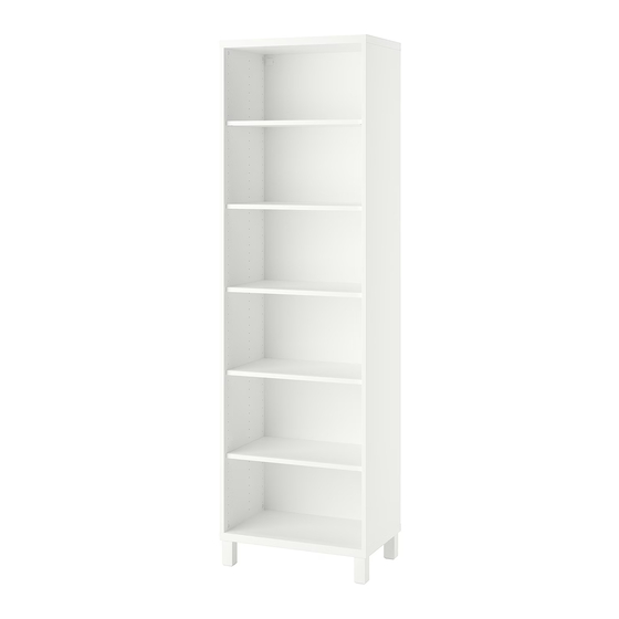
IKEA Besta Manual
Hide thumbs
Also See for Besta:
- Instructions manual (28 pages) ,
- Assembly instructions manual (28 pages) ,
- Manual (24 pages)

Related Manuals for IKEA Besta


Summary of Contents for IKEA Besta
- Page 2 Screwdriver Level Pencil Assembly Help If you need help understanding how to assemble your new BESTA TV shelf contact IKEA. Customer service: 1 (888) 888-4532 Warning Assembly shouldn’t be attempted alone Caution Assembly should be done on...
- Page 3 Parts List Small horizontal Extended head Screw screw (part (part #114928) 16x #114927/115624) x8 Large horizontal screw (part #114926/115263) (part #113301) x12 Shelf base screw Hex head Allen wrench (part #114947 (part #100006) x1 115988) x8 Large L-Bracket (part Screw (part #124424) x4 #113287) x8 L-Bracket...
- Page 4 Pointed Screw (part Slotted Strip Holder #109049) x2 (Part #124187) x8 Strip (Part #124175/124174) Slotted Strip (Part #124173/124172) Slotted Strip (Part #124171/124170) Long Slotted Strip (Part #124169/124168)
- Page 5 Assembly Instructions Note: If you are wall mounting this piece, you will not need the 8 Shelf base screws. Step 1 A. Before assembling, turn base piece upside down B. Attach 8 Shelf base screws (part #114947 115988) to all screw holes in the base piece of the shelf.
- Page 6 Step 2 Turn the base piece back upright, and place the 8 screws (part #113287) into the 8 holes positioned along the long sides of the base piece. NOTE: These are positioned on both long sides at both ends and 1/3 and 2/3 of the length (4 per side as shown to the left).
- Page 7 Step 4 A. Attach two more vertical shelf pieces on the remaining two sets of screws in the base, B. Screw in two large horizontal screws (part #114926 115263) into each piece as shown to the left. Step 5 Now take the top piece of the shelf and screw in the 8 remaining extended head screws (part #114928) from the top side as shown to the left.
- Page 8 Step 6 A. Take the top piece of the shelf and attach it to the rest of the shelf, leaving a small gap along the back side as shown above on the left. B. Take your 4 remaining large horizontal screws(part #114926 115263) and attach them to the top side of the 2 inside vertical pieces.
- Page 9 Step 8 A. Rotate the shelf 180 degrees so that the slider bar faces you. B. Place the clips (#124187) on the slider bar by putting the top lip in the top compartment, then rotating the clip downwards into the bottom compartment until it clicks in.
- Page 10 Step 10 Attach the flat pieces with slots (#124168 - #124173). The longest pieces (#124168 and 124169) go all the way at the end with two on each side. Attach them to the clips by positioning the pieces vertically with the hooks on the bottom and facing towards the shelf.
- Page 11 Note: If you want to mount a television to the shelf, consult the UPPLEVA manual. Cords can go in between the clips and the slotted pieces as shown to the left.
- Page 12 Insert the shelf pegs (#113301) into the holes on the inside of the shelf at desired height. Place shelf piece on top of pegs and slip the holes over the shelf pegs. Note: For leg attachment instructions, see the BESTA Leg Manual. Warning: Do not throw the instructions away.
- Page 14 Tools Required for Assembly Philips Head Screwdriver Assembly Help For assistance assembling your BESTA, contact IKEA. Customer service: 1 (888) 888-4532...
- Page 15 This BESTA leg set comes with 9 leg assemblies, but note that you may only need 8 legs to properly assemble your cabinet. Contains 9 leg bases and 9 leg extensions...
-
Page 16: Parts List
Parts List Leveling screw Hex head screw (part #118157) x2 (part #105323) x2 Small Phillips head Hex head Allen screw (part wrench (part #106632) x2 #100049) x1... - Page 17 Assembly Instructions Step 1 A. Before assembling legs on cabinet, turn cabinet upside down in order to attach legs. B. Use the Allen wrench (#100049) to attach leg base to bottom of cabinet using hex head screw (#105323) to secure. Repeat process for all 4 legs.
- Page 18 Step 2 Slide leg extensions over leg base and secure with the small Phillips screw (#106632) place in the side of the leg extension. Repeat this step for all 4 leg...
- Page 19 Step 3 A. Place leveling screw (#118157) in the end of the leg extension. Turn in at least four (4) turns. Repeat for all 4 leg extensions. B. Once legs are securely attached, turn cabinet back to its right side up position and used leveling screws to stabilize cabinet.
- Page 21 Tools Required for Assembly Philips Head Screwdriver Warning Place assembly parts on a matt or rug to avoid damage due to impact with a hard surface. Assembly Help For assistance assembling your POANG, contact IKEA. Customer service: 1 (888) 888-4532...
- Page 22 Short shank Long shank screw (part screw (part #122607/122603) #122606) 4x Alignment pin Small hex screw (part #123785) (part #119046) Hex head Allen Anchor nut (part Wrench (part #100514) 4x #100001) 1x Spacing washer Tapered head (Part #102319) screw (part #112522) 6x...
- Page 23 This picture shows the placement of all the pieces in the final assembly.
- Page 24 Step 1 Insert the mounting tabs of the four backrest rails into one of the side rails. Make sure that the one with the grip strip is positioned under the top rail. Make sure that the rails are oriented as shown in picture (i) above.
- Page 25 Step 2 Insert the other mounting tabs of the backrest rails into the other side rail. Step 3 Insert the small hex screw (#119046) through the side backrest rail hole and start threads by hand. Use the Allen wrench (#100001) to tighten the screw. Repeat for all 4 holes.
- Page 26 Step 4 Flip the assembly over and tighten the screws on the other side using Allen wrench (#100001) Step 5 A. Slide two chair rails into the fabric for the chair. Make sure that the rails have the curve facing down as shown in picture (i) above.
- Page 27 Step 6 Insert a tapered head screw (#112522) into the hole in the side chair rail and start threads by hand. Use the Allen wrench (#100001) to tighten the screw. Repeat for all 4 holes. Step 7 Position the chair and backrest as shown above. Insert a tapered head screw (#112522) into the hole in the side chair rail and start threads by hand.
- Page 28 Step 8 A. Position the chair and backrest assembly on its side. B. Insert the alignment pin (#123786) in the open hole on the chair. C. Mount the leg on the other end of the alignment pin. Rotate the leg until the other hole on the leg is lined up with the hole on the backrest.
- Page 29 Step 9 A. Obtain one of the support rails. B. Insert anchor nut (#100514) into one end with a flathead screwdriver. C. Insert the mounting tabs of the support rail into the corresponding holes on the chair leg. D. Insert long shank screw (#122606) into the hole in the leg. Push it down until you feel contact with the threaded insert in the support rail.
- Page 30 Step 10 A. Flip the chair over on its other side. B. Insert alignment pin (#123786) in the open hole on the seat. C. Mount the leg on the other end of the alignment pin. Rotate the leg until the mounting tabs on the support rails and the hole on the backrest are aligned.
- Page 31 Step 11 A. Insert anchor nut (#100514) into the open hole of the support rail with a flathead screwdriver. B. Insert long shank screw (#122606) into the hole in the leg. Push screw down until you feel contact with the anchor nut in the support rail. C.
- Page 32 Use Allen wrench (#100001) and ensure that the three fasteners circled above are tight. Check the fasteners on both sides of the chair. There are 6 fasteners total. Make sure that the grip strip on the cushion is aligned with the grip strip on the backrest.
Need help?
Do you have a question about the Besta and is the answer not in the manual?
Questions and answers