Table of Contents
Advertisement
Quick Links
Advertisement
Chapters
Table of Contents

Subscribe to Our Youtube Channel
Related Manuals for IAI Rec

Summary of Contents for IAI Rec
- Page 1 System Instruction Manual First Edition ME0394-1A System Configuration Chapter and Specifications EC Gateway Unit Chapter EC Connection Unit Chapter Unit connection- Installation and Wiring Chapter Operation Chapter Parameter Chapter Troubleshooting Chapter...
- Page 3 ● This instruction manual is an original document dedicated for this product. ● This product cannot be used in ways not shown in this instruction manual. IAI shall not be liable for any result whatsoever arising from the use of the product in any other way than what is noted in the manual.
- Page 4 REC System Instruction Manual Configuration Control Product name Instruction manual name number REC System First Step Guide ME0395 REC System Instruction Manual (this document) ME0394 RCON System ME0384 Instruction Manual RCM-101-MW/RCM-101-USB PC software ME0155 Instruction Manual Touch Panel Teaching Pendant...
- Page 5 Chapter 4 Unit connection / Installation and Wiring In this chapter, explains how to link units, install them and how to lay out wiring for REC System. Chapter 5 Operation In this chapter, explains about control signals, how to operate and behaviours of ELECYLINDER.
- Page 6 Contents Safety Guide ·················································································· Intro-1 Precautions for Handling ··································································· Intro-8 Precautions for PC connection to REC gateway unit grounded at positive terminal of 24 VDC power supply ···························· Intro-11 International Standard Compliance ······················································ Intro-13 Warranty ························································································ Intro-14 Actuator Coordinate System ······························································ Intro-16 Chapter 1 System Configuration and Specifications Overview ················································································...
- Page 7 4.2.2 Unit connection ······················································································· 4-4 4.2.3 Unit mounting ························································································· 4-5 Wiring method ········································································· 4-6 4.3.1 Power supply wiring to REC system ···························································· 4-6 4.3.2 REC System Connection Cable ································································· 4-8 4.3.3 Wiring between Actuator and EC Connection Unit ·········································· 4-9 4.3.4 Example of Wiring for Field Network ···························································...
- Page 8 Chapter 7 Troubleshooting Troubleshooting ······································································· 7-1 EC Gateway Unit Alarm Causes and Countermeasures ··················· 7-2 7.2.1 Causes and countermeasures of individual alarms ········································· 7-2 Causes and countermeasures for ELECYLINDER alarms ················· 7-5 7.3.1 Alarm Group ··························································································· 7-5 7.3.2 Troubleshooting for alarm groups ······························································· 7-6 Revision history ··············································································...
- Page 9 Safety Guide Safety Guide The Safety Guide is intended to permit safe use of the product and thus to prevent risks and property damage. Be sure to read it before handling the product. Safety Precautions for Our Products Common safety precautions for the use of robots in various operations are indicated here. Operation Precautions ●...
- Page 10 Safety Guide Operation Precautions ● When transporting heavy objects, do the work with two or more persons or Transportation utilize equipment such as a crane. ● When working with two or more persons, make it clear who is to be in charge and communicate well with each other to ensure safety.
- Page 11 Installation (2) Cable wiring and Startup ● Use IAI genuine cables for connecting the actuator and controller, and for the teaching tools. ● Do not scratch cables, bend them forcibly, pull them, coil them, snag them, or place heavy objects on them. Otherwise, this may lead to fire, electric shock, or abnormal operation due to leakage or conduction malfunction.
- Page 12 Safety Guide Operation Precautions Installation (4) Safety measures ● When working with two or more persons, make it clear who is to be in charge Startup and communicate well with each other to ensure safety. ● When the product is operating or in the ready mode, take safety measures (such as the installation of safety/protection fences) so that nobody can enter the area within the robot's movable range.
- Page 13 Safety Guide Operation Precautions ● When working with two or more persons, make it clear who is to be in charge Trial Operation and communicate well with each other to ensure safety. ● After teaching or programming, carry out trial operation step by step before switching to automatic operation.
- Page 14 Safety Guide Operation Precautions ● When working with two or more persons, make it clear who is to be in charge Maintenance and communicate well with each other to ensure safety. ● Perform the work outside the safety/protection fence, if possible. If operation Inspection must be performed within the safety/protection fence, prepare "Work Regulations"...
- Page 15 Safety Guide Precaution Indications The safety precautions are divided into "Danger", "Warning", "Caution" and "Notice" according to the warning level, as follows, and described in the Instruction Manual for each model. Level Degree of risk to persons and property Symbol This indicates an imminently hazardous situation which, if the Danger Danger...
- Page 16 Precautions for Handling Precautions for Handling Make sure to follow the usage condition, environment and specification range of the product. In case it is not secured, it may cause a drop in performance or malfunction of the product. Use the correct teaching tool. Refer to the following item and use compatible tools for PC software and teaching pendant usable for this controller.
- Page 17 Precautions for Handling Creation of sequence programs When creating a sequence program, be careful of the following. If exchanging data between devices with different scan time, the length of time required for a reliable signal reading process is greater than the longer scan time. (In order to safely perform the reading process on the PLC side, we recommend using a timer set value of at least twice the longer scan time.) ●...
- Page 18 The minimum set value of the 10 ms timer should be "2", and when required to set to 100 ms, use the 10 ms timer and set it to "10". External communication ports The REC gateway unit has 2 types of communication port. • SIO port (RS-485 round connector) • USB port (USB mini-B connector) Do not connect multiple ports and perform communication simultaneously.
- Page 19 Precautions for PC connection to REC gateway unit grounded at positive terminal of 24 VDC power supply Precautions for PC connection to REC gateway unit grounded at positive terminal of 24V DC power supply If the EC gateway unit is grounded at the positive terminal of the 24 VDC power supply, a PC cannot be connected to the USB connector (mini-B) of the EC gateway unit.
- Page 20 Precautions for PC connection to REC gateway unit grounded at positive terminal of 24 VDC power supply If the gateway unit is grounded at the positive terminal of the 24V DC power supply, use an SIO isolator (RCB-ISL-SIO) as shown in the diagram below when connecting a PC to the SIO connector of the gateway unit.
- Page 21 This product complies with the following overseas standards. Refer to the Overseas Standard Compliance Manual (ME0287) for more detailed information. RoHS Directive CE Marking UL Certification ○ To be Complied Soon To be Complied Soon * Please contact IAI for more details. Intro-13 ME0394-1A...
- Page 22 Our products are covered by warranty when all of the following conditions are met. Faulty products covered by warranty will be replaced or repaired free of charge: (1) The breakdown or malfunction in question pertains to our product as delivered by IAI or our authorized dealer.
- Page 23 (4) Equipment used to handle cultural assets, art or other irreplaceable items (3) Contact IAI in advance if our product is to be used in any condition or environment that differs from that specified in the catalog or instruction manual.
- Page 24 ● For models with which change is not possible, the actuator must be replaced. Contact IAI if anything is unclear. The 0 in the figure below shows home. The parentheses show home reverse specification. (1) Rod type...
- Page 25 Actuator Coordinate System (4) Rotary type (330-degree rotation specification) 330° Intro-17 ME0394-1A...
-
Page 26: Table Of Contents
Configuration Unit List ·········································· 1-4 Specifications ····················································· 1-5 1.5.1 General specifications ············································· 1-5 1.5.2 Power supply capacity ············································· 1-7 1.5.3 Inrush current ························································ 1-10 1.5.4 Drive Cutoff Circuit ·················································· 1-11 1.5.5 Installation conditions ·············································· 1-13 External dimensions ············································· 1-16 1.6.1 REC system ·························································· 1-16... -
Page 27: Overview
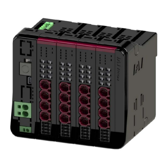
1.1 Overview 1.1 Overview REC System is capable to control 16 axes of ELECYLINDER at the maximum in the field network of the host programable controller (hereinafter described as the PLC). The system is to be constructed with combinations of EC units capable to connect four axes per each between the EC gateway unit that is an interface for the field network connection and the terminal unit (terminal resistor). -
Page 28: Features
The actuator body can register individual actuator information. The individual information can be checked at IAI even if the actuator is removed from the controller and returned. (6) Improved usability Equipped with a USB port as standard. -
Page 29: System Configuration
1.3 System Configuration 1.3 System Configuration The following shows the system configuration. Field network Teaching tool Model :TB-02 Model :RCM-101-MW TB-03 RCM-101-USB Power supply unit Model:PSA-24 Connectable actuators ME0394-1A... -
Page 30: Configuration Unit List
1.4 Configuration Unit List 1.4 Configuration Unit List The units that configure the REC system are listed below. Product name Model EC Gateway unit CC-Link connection type REC-GW-CC CC-Link IE Field connection type REC-GW-CIE DeviceNet connection type REC-GW-DV EtherCAT connection type... -
Page 31: Specifications
1.5 Specifications 1.5 Specifications 1.5.1 General specifications The specifications regarding installation conditions are listed below. Item Specifications Ambient operating 0 to 55℃ temperature Ambient operating 85% RH or less, non-condensing humidity Ambient storage -20 to 70°C temperature Operating atmosphere Avoid corrosive gas and in particular avoid excessive dust Altitude 1,000m or less Frequency: 10 to 57 Hz/Amplitude: 0.075mm,... - Page 32 1.5 Specifications The specifications regarding control are listed below. Item Specifications Number of controlled 1 to 16-axis axes Encoder Incremental resolution Stepper motor Battery-less Absolute [pulse/r] Cable length Motor/encoder cable: 10 m or less Field network CC-Link, CC-Link IE Field, DeviceNet, EtherCAT, EtherNet/IP, PROFIBUS-DP, interface PROFINET IO Communication method...
-
Page 33: Power Supply Capacity
1.5 Specifications 1.5.2 Power supply capacity Power capacity is divided into two parts, control power capacity and motor power capacity. Power supply to each unit should be input from the 24V power supply connector on the EC gateway unit. The necessary power capacity is calculated from adding the "total control power capacity of the unit in use"... - Page 34 Check that the results from the calculations of the control power supply and the motor power supply based on the construction of REC System would not exceed the current limit. Note that the EC gateway unit is not included in the calculations.
- Page 35 Be mindful of the in-rush current of the 24V DC power supply unit and the rated interrupting current of the circuit breaker when select. Rated Interrupting Current > Short-Circuit Current = Primary Side Current Amperage ÷ Power Supply Voltage [In-Rush Current of IAI Power Supply Unit PSA-24] Item Conditions...
-
Page 36: Inrush Current
1.5 Specifications 1.5.3 Inrush current In-rush current would occur only on the EC connection unit. The inrush current values are listed below. Item Specifications Inrush current (About 5 ms) RCON-EC Max. 40.0A When multiple driver units are used, depending on the capacity of the 24V DC power source, a voltage drop might occur when the units are turned on. -
Page 37: Drive Cutoff Circuit
1.5.4 Drive Cutoff Circuit Shown below is a circuit related to the drive cutoff in REC System. Although REC System is supplied with 24V power from the EC gateway unit, the circuit related to the drive cutoff is on the EC connection unit side. - Page 38 1.5 Specifications [Stop Circuit] There are two ways as shown below to make a compulsory stop for ELECYLINDER in REC System. (1) To stop all the axes of ELECYLINDER connected at once by pressing and holding the stop switch on a teaching pendant (wired connection).
-
Page 39: Installation Conditions
1.5 Specifications 1.5.5 Installation conditions [Installation Environment] Usage is possible in environments of pollution degree 2 or equivalent. *1 Pollution degree 2: Environment in which generally only nonconductive pollution occurs, but temporary conductive pollution may occur due to condensation. (IEC60664-1) (1) Installation environment Avoid the following locations for installation. - Page 40 1.5 Specifications [Installation and mounting] Consider the size of the control panel, placement of the REC controller, cooling and the like when designing and manufacturing so that the ambient temperature is 0 to 55°C. Item Specifications Item Specifications Installation direction...
- Page 41 1.5 Specifications [Noise countermeasures and mounting method] (1) Grounding for noise countermeasures (frame ground) Connect the ground wire to the FG terminal block of the main Controller body. Push in the square hole with a screwdriver or the like to connect. Annealed copper wire: 1.6 mm Controller diameter...
-
Page 42: External Dimensions
1.6 External dimensions 1.6 External dimensions 1.6.1 REC system Item Specifications W133 mm × H115 mm × D95 mm External dimensions (when four units of EC connection unit) Mass About 675g (when four units of EC connection unit) External view See figure below 98.8... - Page 43 R E C Chapter EC Gateway Unit Overview ··························································· 2-1 How to Read the Model Number ····························· 2-2 2.2.1 How to read the model nameplate ······························ 2-3 EC Gateway Unit and Accessories ·························· 2-4 Part Names/Functions and External Dimensions ········ 2-5 2.4.1 Part names ····························································...
- Page 44 Field Network General Specifications ······················· 2-16 2.5.1 CC-Link ································································ 2-16 2.5.2 CC-Link IE Field ····················································· 2-17 2.5.3 DeviceNet ····························································· 2-18 2.5.4 EtherCAT ······························································ 2-19 2.5.5 EtherNet/IP···························································· 2-20 2.5.6 PROFIBUS-DP ······················································ 2-21 2.5.7 PROFINET IO ························································ 2-22...
-
Page 45: Overview
ELECYLINDER to the field network of the host PLC. It supports 7 kinds of field networks (CC-Link, CC-Link IE Field, DeviceNet, EtherCAT, EtherNet/IP, PROFIBUS-DP, PROFINET IO). By connecting the EC connection units (RCON-EC) to REC System, it is available to connect 16 axes at the maximum. -
Page 46: How To Read The Model Number
How to Read the Model Number 2.2 How to Read the Model Number The model of the EC gateway unit is as follows. EC Gateway unit model - - - Type I/O Type Options Standard type CC-Link connection specification Without terminal unit CC-Link IE Field connection specification DeviceNet connection specification EtherCAT connection specification... -
Page 47: How To Read The Model Nameplate
2.2 How to Read the Model Number 2.2.1 How to read the model nameplate [EC Gateway Unit] [Nameplate Location] Model number → Serial number → Type↑ ↑Serial number Mark Explanation of Mark Use IAI specified cables only. [Terminal Unit] [Nameplate Location] ME0394-1A... -
Page 48: Ec Gateway Unit And Accessories
The following table shows the product configuration for the standard specification. See the packing list for the details of the enclosed components. In the unlikely case that any model number errors or missing parts come to light, contact your local IAI distributor. Part name... -
Page 49: Part Names/Functions And External Dimensions
2.4 Part Names/Functions and External Dimensions 2.4 Part Names/Functions and External Dimensions 2.4.1 Part names REC-GW T RUN LED SYS LED AUTO/MANU switch FIELDBUS T.P. connector STOP LED USB connector MODE LED C ERR LED 24V power connector STATUS 0 LED... - Page 50 2.4 Part Names/Functions and External Dimensions Connector upper part DIN tab Connector Connector bottom part Left side Right side Rear ME0394-1A...
-
Page 51: Led Display
2.4 Part Names/Functions and External Dimensions 2.4.2 LED display LED for indicating EC gateway unit status and field network status. Panel Display Status Description notation color Light ON Normal internal bus communication Green Blinking Waiting for initialization signal T RUN Orange Light ON Bus communication error generated... -
Page 52: Auto/Manu Switch
2.4 Part Names/Functions and External Dimensions 2.4.3 AUTO/MANU switch Switches between automatic and manual operation. Symbol Description Online operation mode that enables reception of commands from AUTO host devices such as PLCs Teaching operation mode that enables reception of commands from MANU host devices such as PLCs Caution... -
Page 53: Sio Connector
2.4 Part Names/Functions and External Dimensions 2.4.4 SIO connector A connector for connecting the teaching pendant to PC software. PC software can also be connected with a USB. Pin No. Signal name Description TP_SD+ Teaching pendant/PC RS-485 differential signal + side TP_SD- Teaching pendant/PC RS-485 differential signal - side Teaching pendant 5 V output... -
Page 54: Usb Connector
2.4 Part Names/Functions and External Dimensions 2.4.5 USB connector It is a connector to be connected to the PC software or gateway parameter configuration tool. For use, it is necessary to install the USB connection driver for RCON. For how to install the driver, refer to “PC software Instruction Manual (ME0155)”. Connector name: 51387-0530 (Molex) Pin No. -
Page 55: Power Connector
2.4 Part Names/Functions and External Dimensions 2.4.6 24V power connector Motor power +24 V supply connector. Supplies power to the motor of the driver unit linked to the EC gateway unit. Pin No. Signal name Description Motor power +24 V input Motor power connector compatible wire Item Specifications... -
Page 56: Field Network Connector
2.4 Part Names/Functions and External Dimensions 2.4.7 Field network connector A connector for connecting to field networks. Field network details are listed in "2.5 Field Network General Specifications)". 2.4.8 Connectors A connector for use between units. Two identical connectors are used. The connectors have a floating structure that absorbs connector misalignment due to housing mating or mounting misalignment between connectors. -
Page 57: Terminal Unit
2.4 Part Names/Functions and External Dimensions 2.4.9 Terminal unit RCON-GW-TRE Terminal Unit Card Connector Left side Right side Rear 2-13 ME0394-1A... -
Page 58: External Dimensions
2.4 Part Names/Functions and External Dimensions 2.4.10 External dimensions EC Gateway unit Item Specifications External dimensions W 30 mm × H 115 mm × D 95 mm Mass About 135g External view See figure below 98.8 2-14 ME0394-1A... - Page 59 2.4 Part Names/Functions and External Dimensions Terminal unit Item Specifications External dimensions W 12.6 mm × H 115 mm × D 95 mm Mass About 48g External view See figure below 12.6 98.8 2-15 ME0394-1A...
-
Page 60: Field Network General Specifications
2.5 Field Network General Specifications 2.5 Field Network General Specifications 2.5.1 CC-Link Cable connector name: MSTB2.5/5-STF-5.08 AU (Phoenix Contact) Pin No. Signal name Description Signal line A Signal line B Digital ground Connects the shield of shielded cables (This connector's 5-pin FG and the control power connector's 1 pin FG are connected internally) Frame ground (This connector's 4-pin SLD and the control power... -
Page 61: Cc-Link Ie Field
2.5 Field Network General Specifications 2.5.2 CC-Link IE Field L.ER LINK L.ER LINK Cable/connector specifications: Ethernet ANSI/TIA/EIA-568-B Category 5e or higher, shielded 8P8C modular plug (RJ45) * It is to be prepared by the customer. LED display Panel Display Name Status Description notation... -
Page 62: Devicenet
2.5 Field Network General Specifications 2.5.3 DeviceNet Cable connector name: MSTB2.5/5-STF-5.08 AU M (Phoenix Contact) Pin No. Pin color scheme Description Black Power supply cable - side Blue Signal data Low side - Digital Ground White Signal data High side Power supply cable + side LED display Panel... -
Page 63: Ethercat
2.5 Field Network General Specifications 2.5.4 EtherCAT Cable/connector specifications: Ethernet ANSI/TIA/EIA-568-B Category 5 or higher, shielded 8P8C modular plug (RJ45) * It is to be prepared by the customer. LED display Panel Display Name Status Description notation color Light ON Signal component (module) error Blinking Configuration information (settings) error... -
Page 64: Ethernet/Ip
2.5 Field Network General Specifications 2.5.5 EtherNet/IP Cable/connector specifications: Ethernet ANSI/TIA/EIA-568-B Category 5 or higher, shielded 8P8C modular plug (RJ45) * It is to be prepared by the customer. LED display Panel Display Name Status Description notation color Light ON Normal operation Green No configuration information,... -
Page 65: Profibus-Dp
2.5 Field Network General Specifications 2.5.6 PROFIBUS-DP Cable side connector name: 9-pin D sub connector (male) * It is to be prepared by the customer. Pin No. Signal name Description Not connected Not connected B-Line Signal line B (RS-485) Transmission request 0 V (isolated) +5 V +5 V output (isolated) -
Page 66: Profinet Io
2.5 Field Network General Specifications 2.5.7 PROFINET IO Cable/connector specifications: Ethernet ANSI/TIA/EIA-568-B Category 5 or higher, shielded 8P8C modular plug (RJ45) * It is to be prepared by the customer. LED display Panel Display Name Status Description notation color Light ON Normal communication Blinking Network being diagnosed... - Page 67 R E C Chapter EC Connection Unit Overview ··························································· 3-1 How to Read the Model Number ····························· 3-2 3.2.1 How to read the model nameplate ······························ 3-3 Components ······················································· 3-4 Part Names/Functions and External Dimensions ········ 3-5 3.4.1 Part names ···························································· 3-5 3.4.2 LED display ···························································...
-
Page 68: Overview
3.1 Overview 3.1 Overview EC connection unit is the ELECYLINDER connection unit dedicated for R Unit. Connecting RCON-EC connection type (Option: ACR) ELECYLINDER to EC connection unit, ELECYLINDER can be controlled in the field network communication. Also, the maximum number of ELECYLINDER available to be connected to one unit of the EC connection unit should be four axes. -
Page 69: How To Read The Model Number
3.2 How to Read the Model Number 3.2 How to Read the Model Number EC Connection Unit model - - RCON Type Number of Axes ELECYLINDER Four-axis type *ELECYLINDER capable to be connected to the EC connection unit is the option: ACR only. E C - - A C R <Series>... -
Page 70: How To Read The Model Nameplate
3.2 How to Read the Model Number 3.2.1 How to read the model nameplate [EC Connection Unit] [Nameplate Location] → Model number → Serial number Caution Mark Type→ ↑Serial number Mark Explanation of Mark Use IAI specified cables only. ME0394-1A... -
Page 71: Components
The following table shows the product configuration for the standard specification. See the packing list for the details of the enclosed components. In the unlikely case that any model number errors or missing parts come to light, contact your local IAI distributor. [EC Connection Unit]... -
Page 72: Part Names/Functions And External Dimensions
3.4 Part Names/Functions and External Dimensions 3.4 Part Names/Functions and External Dimensions [EC Connection Unit] 3.4.1 Part names Forward end LED (1st to 4th Axes) T RUN LED Backward end LED (1st to 4th Axes) SYS LED Jog switch Brake Release Switch (1st to 4th Axes) (1st to 4th Axes) Drive source shutoff connector... - Page 73 3.4 Part Names/Functions and External Dimensions Connector upper part Connector Connector Connector bottom part DIN tab Left side Right side Rear ME0394-1A...
-
Page 74: Led Display
3.4 Part Names/Functions and External Dimensions 3.4.2 LED display Display Panel notation Status Description color Light ON Normal internal bus communication Green T RUN Blinking Waiting for initialization signal, initialization communication failed Orange Light ON Bus communication error generated Light ON Servo ON Green Blinking... -
Page 75: Jog Switch
● The jog switch is disabled when the communication with the teaching tool is disconnected while the screen in which the actuator can be operated with the teaching tool is opened. ● To enable jog switch operation again, turn the REC system on again or perform software reset. ME0394-1A... -
Page 76: Brake Release Switch
3.4 Part Names/Functions and External Dimensions 3.4.4 Brake release switch They are switches to release the brake compulsorily. It comes the switches for 1st, 2nd, 3rd and 4th axes from the top. Should be on NOM side during normal operation. On NOM side, the brake will be released by servo ON and locked by servo OFF. -
Page 77: Connectors For Ec Connection
3.4 Part Names/Functions and External Dimensions 3.4.5 Connectors for EC Connection They are connectors to connect ELECYLIDER. It comes the connectors for 1st, 2nd, 3rd and 4th axes from the top. Axis numbers for four axes should be assigned to the EC connection unit even if ELECYLINDER is not connected to all of four. -
Page 78: Drive Source Shutoff Connector
3.4 Part Names/Functions and External Dimensions 3.4.6 Drive source shutoff connector Drive-source cutoff input. Drive source can be cut off by individual axes. Cable connector name: DFMC1.5/2-ST-3.5 (Phoenix Contact) Pin No. Signal name Description MPO_3 Motor power output 4th axes MPO_2 Motor power output 3rd axes MPO_1... -
Page 79: Connectors
3.4 Part Names/Functions and External Dimensions 3.4.7 Connectors A connector for use between units. Two identical connectors are used. The connectors have a floating structure that absorbs connector misalignment due to housing mating or mounting misalignment between connectors. Plug side connector Receptacle connector 3-12 ME0394-1A... -
Page 80: External Dimensions
3.4 Part Names/Functions and External Dimensions 3.4.8 External dimensions [EC Connection Unit] Item Specifications External dimensions W 22.6 mm × H 115 mm × D 95 mm Mass About 123g External view See figure below 22.6 98.8 3-13 ME0394-1A... - Page 81 4.2.2 Unit connection ······················································ 4-4 4.2.3 Unit mounting ························································ 4-5 Wiring method ···················································· 4-6 4.3.1 Power supply wiring to REC system ··························· 4-6 4.3.2 REC System Connection Cable ································· 4-8 4.3.3 Wiring between Actuator and EC Connection Unit ········· 4-9 4.3.4 Example of Wiring for Field Network ···························...
-
Page 82: Tools To Use
4.1 Tools to Use 4.1 Tools to Use The tools used for constructing and starting up the REC system are PC software or a teaching pendant, and the gateway parameter configuration tool. In this chapter, explains the EC connection unit (RCON-EC). - Page 83 For an example of using and details the gateway parameter configuration tool, refer to "5.4 How to Use the Gateway Parameter Configuration Tool (page 5-24)" Also, “Quick Start Guide” explaining how to set up each network is available to download from IAI homepage. (Quick Start Guide available in Japanese only) ME0394-1A...
-
Page 84: Unit Connection / Installation
Check the following descriptions and then make a selection for each unit. (1) Unit arrangement The REC system has a unit-connecting configuration. Each of the units has the same connector and the same locking configuration, which allows the units to be connected in any order. -
Page 85: Unit Connection
4.2 Unit connection / Installation 4.2.2 Unit connection In here, describes how to link units in REC system. It is recommended that the unit link is established before connected to DIN rails. (1) Turn the operating parts of the connector upper/bottom part towards the panel and position on the panel end. -
Page 86: Unit Mounting
4.2.3 Unit mounting REC System is available only with DIN rail installation. Pull down the DIN tab visible from the lower part of the housing rear (red color part in a dashed line in the figure below), mount on the DIN rail, then push the DIN operating part upward to lock it. -
Page 87: Wiring Method
4.3.1 Power supply wiring to REC system To supply power to the REC system, power supply wiring to the EC gateway unit is required. Here is an example of wiring for the EC gateway unit to IAI 24V DC power supply unit. - Page 88 4.3 Wiring method [Electric wire diameter used for EC gateway unit power supply wiring] For the wires to be connected to the power connector, use the following applicable wires. Compatible wire Connector Signal name Compatible wire diameter AWG20 to 8 (Copper wire) AWG20 to 12 (Copper wire) AWG14 to 12 (Copper wire) * Use cables with their rated temperature on the isolation sheath at 60°C or higher.
-
Page 89: Rec System Connection Cable
* The cable lengths should be 1m at shortest and 10m at longest. Order can be made in every 1m of length. * Shown below is an example for the model types. Cable Length 1m → CB-REC (2) -PWBIO010-RB Cable Length 3m → CB-REC- (2) PWBIO030-RB Cable Length 10m → CB-REC- (2) PWBIO100-RB... -
Page 90: Wiring Between Actuator And Ec Connection Unit
EC connection unit. Push the connectors inward till it makes "click" sound. The axis number should be determined by the position of the connector on the EC connection unit. EC Connection Unit REC System Insert until it ELECYLINDER Connection Cable clicks CB-REC-PWBIO***-RB... -
Page 91: Example Of Wiring For Field Network
4.3 Wiring method 4.3.4 Example of Wiring for Field Network In this manual, shows an example to establish connection to the CC-Link master unit using a PLC manufactured by Mitsubishi Electric as the host PLC. [Connecting the host PLC and two systems] Connection example Host PLC... - Page 92 4.3 Wiring method [CC-Link dedicated cable and cable connector wiring method] (1) Prepare a CC-Link dedicated cable. (2) Strip 7mm of insulation from each wire end. 7mm (3) Insert the stripped wiring in the direction of the arrow in the figure below to the back of the connector and tighten with a flathead screwdriver.
-
Page 93: Each Field Network Wiring
4.3 Wiring method 4.3.5 Each field network wiring For details of the connection method, follow the instruction manuals of the master unit of each field network and the PLC configured. [CC-Link] Shield (SLD) Yellow (DG) White (DB) Blue (DA) Controller side Connector top view Connector name CC-Link cable connector... - Page 94 4.3 Wiring method [CC-Link IE Field] L.ER LINK L.ER LINK Controller side Connector top view Connector name CC-Link IE Field cable connector Remarks Ethernet ANSI/TIA/EIA-568-B Category 5e or higher shielded To be prepared Cable side 8P8C modular plug (RJ-45) by the customer Ethernet ANSI/TIA/EIA-568-B Category 5e or higher shielded Controller side 8P8C modular jack (RJ-45)
- Page 95 4.3 Wiring method [DeviceNet] Red (V+) White (CAN H) Shield Blue (CAN L) Black (V-) Controller side Connector top view Connector name DeviceNet cable connector Remarks Standard Cable side MSTB2.5/5-STF-5.08 AU M (Phoenix Contact) accessories Controller side MSTBA2.5/5-GF-5.08 AU (Phoenix Contact) Signal name Compatible Pin No.
- Page 96 4.3 Wiring method [EtherCAT] Controller side Connector top view Connector name EtherCAT cable connector Remarks Ethernet ANSI/TIA/EIA-568-B Category 5 or higher shielded To be prepared Cable side 8P8C modular plug (RJ45) by the customer Ethernet ANSI/TIA/EIA-568-B Category 5 or higher shielded Controller side 8P8C modular jack (RJ45) Pin No.
- Page 97 4.3 Wiring method [EtherNet/IP] [PROFINET IO] Controller side Connector top view Connector name EtherNet/IP, PROFINET IO cable connector Remarks Ethernet ANSI/TIA/EIA-568-B Category 5 or higher shielded To be prepared Cable side 8P8C modular plug (RJ45) by the customer Ethernet ANSI/TIA/EIA-568-B Category 5 or higher shielded Controller side 8P8C modular jack (RJ45) Pin No.
- Page 98 4.3 Wiring method [PROFIBUS-DP] Red B line (positive side) Green A line (negative side) Cable Shield Controller side Connector top view Connector name PROFIBUS-DP cable connector Remarks To be prepared Cable side 9-pin D sub connector (male) by the customer Controller side 9-pin D sub connector (female) Pin No.
-
Page 99: Connection The Teaching Connector
4.3 Wiring method 4.3.6 Connection the teaching connector Connect a teaching pendant such as the PC software. Teaching Mode switch pendant PC connection cable (Supplied with PC software) Teaching connector specification Teaching connector Model Remarks Controller side TCS7587-0121077 Supplied by Hosiden Corporation Cable side mini DIN 8 pin Teaching connector... -
Page 100: Connection The Usb Connector
4.3 Wiring method 4.3.7 Connection the USB connector It is available to use the PC software by connecting a PC to a USB port. USB cable (A, mini-B) (prepared by the customer) USB connection connector specification Connector to be USB mini-B 51387-0530 (Molex) Used... - Page 101 5.2.4 Assignment of EC Connection Unit ····························· 5-11 I/O Signals ························································· 5-14 5.3.1 Input and Output Signal Features in EC Connection Unit ·· 5-14 5.3.2 Caution for REC System ·········································· 5-17 5.3.3 Timing of basic operation ·········································· 5-18 5.3.4 Basic Operations of ELECYLINDER ··························· 5-19 Gateway Parameter Configuration Tool ····················...
-
Page 102: Operation Function
ELECYLINDER via the EC connection unit. [Image of Connection] Connection between PLC and ELECYLINDER (1) Input a movement signal (forward or backward) from PLC to REC (EC connection unit). (2) Input the movement signal from REC (EC connection unit) to each unit of ELECYLINDER. -
Page 103: Address Configuration
5.2 Address Configuration 5.2 Address Configuration The construction of addresses for REC is as shown below. The domains should mainly be divided to the GW unit domains and RCON-EC domains. The addresses occupied by the network should be constructed with one word of the fixed domain and the data domains varied depending on the number of units of the EC connection unit. -
Page 104: Overall Address Configuration Example
5.2.1 Overall address configuration example In here, shows the overall address construction when four units of the EC connection unit are connected to the REC gateway unit. Note that CC-Link and DeviceNet should be assigned to the word addresses while PROFIBUS- DP to the byte addresses. - Page 105 5.2 Address Configuration [For DeviceNet] PLC output ⇒ REC REC ⇒ PLC input Relative CH High byte Low byte High byte Low byte Gateway control signal Gateway status signal Control signal (Unit 0) Status signal (Unit 0) Control signal (Unit 1)
- Page 106 5.2 Address Configuration [For PROFINET IO] PLC output ⇒ REC REC ⇒ PLC input 4-word High byte Low byte High byte Low byte Module count Gateway control signal Gateway status signal Control signal (Unit 0) Status signal (Unit 0) Control signal (Unit 1)
-
Page 107: Gateway Status Signals
5.2 Address Configuration 5.2.2 Gateway status signals The first one word of each input and output in the EC gateway unit address construction should be for a signal to monitor the condition of the EC gateway unit. It is not available for use of an output signal. - Page 108 5.2 Address Configuration I/O signal list Symbol Signal type Content name Control - 15-0 Not available. signal Turns ON if an error occurs that requires the gateway to be restarted. *ALMH (Likely due to a mistaken parameter setting. Confirm as needed.) -...
-
Page 109: Elecylinder Position Table
5.2 Address Configuration 5.2.3 ELECYLINDER Position Table The stop position and operating condition settings are established in ELECYLINDER at the delivery. The stop position and the operation conditions can be adjusted with a teaching tool in the simple data setting window. Reference PC software operating method PC software (RCM-101-*-*) manual (ME0155) - Page 110 5.2 Address Configuration (1) Backward End / Forward End [mm] It is the coordinate values for positioning. Input values from the home position. Registration is available in 0.01mm unit. (2) Acceleration / Velocity / Deceleration ● Acceleration [% or G] Acceleration at the start of operation should be set in a value from 1 to 100%.
- Page 111 5.2 Address Configuration (3) Pressing / Pressing Start Point / Pressing Force ● Pressing Selection can be made from “Positioning Operation” and “Pressing Operation”. When there is a check mark at “Pressing”, it should perform the pressing operation. ● Pressing Start Point [mm] *Displayed only in pressing operation It is the position to start the pressing operation.
-
Page 112: Assignment Of Ec Connection Unit
5.2 Address Configuration 5.2.4 Assignment of EC Connection Unit The assignment of the EC connection unit should be as shown below. The EC connection unit occupies domains for four axes (one word) even though not all of four axes are connected. PLC output = Axis control signal Address 1 word = 16 bits... - Page 113 5.2 Address Configuration [I/O Signal List] EC Connection Unit (ON = corresponding bit is "1", OFF = corresponding bit is "0") Signal type Signal name Content Details - Not available - Alarm Cancel Page [Alarm cancelled with on] 5-15 Drive Forward [Drives forward with on (drives forward Page after home-return operation when home...
- Page 114 5.2 Address Configuration [I/O Signal List] EC Connection Unit (ON = corresponding bit is "1", OFF = corresponding bit is "0") Signal type Signal name Content Details Operation Ready Page E3RD [On: Operation ready (servo on)] 5-16 Alarm (break contact) Page *ALM [ON:No alarm、OFF:Alarm generated]...
-
Page 115: I/O Signals
5.3 I/O Signals 5.3 I/O Signals 5.3.1 Input and Output Signal Features in EC Connection Unit The input and output signals for the EC connection unit are as shown below. On means the applicable bit is "1" while off means "0". [1] Movement command input backward end/forward end (ST0/ST1) PLC output signal The ST signal function automatically switches depending on whether the unit has completed home return or not. - Page 116 5.3 I/O Signals [2] Alarm clear input (RES) PLC output signal ● When the [RES] signal is turned ON, the currently triggered alarm will be cleared. ● Alarm clear may not be possible depending on the alarm itself. Refer to "7.3.2 Troubleshooting for alarm groups" for detail. [3] Position detection output backward end/forward end (LS0/LS1) PLC input signal ●...
- Page 117 5.3 I/O Signals [4] Pressing complete output backward end/forward end (PE0/PE1) PLC input signal ● Turns ON when "pressing complete" is determined during pressing operation. ● Turns OFF if no contact can be made. [5] Alarm output (*ALM) PLC input signal ●...
-
Page 118: Caution For Rec System
5.3 I/O Signals 5.3.2 Caution for REC System Described below is a caution in REC System use. ● The EC connection unit occupies domains for four axes (one word) even though not all of four axes are connected. Also, an axis number that an axis is not connected should not be pulled one number forward. -
Page 119: Timing Of Basic Operation
5.3 I/O Signals 5.3.3 Timing of basic operation The procedure from turning on the REC system to the home return command is as follows. (1) Supply 24V power (24V DC). (2) Confirm that the gateway status signal "*ALMH" and operation standby complete signals "E0RD"... -
Page 120: Basic Operations Of Elecylinder
5.3 I/O Signals 5.3.4 Basic Operations of ELECYLINDER [Home return operation/positioning operation] Turning the [ST0] signal ON when home return is not complete will first trigger home return operation. After a momentary stop at the home position, it will then move to the backward end. As well, when the [ST1] signal is turned ON, the unit will move to the forward end after home return operation. - Page 121 5.3 I/O Signals This shows the PLC timing chart for operating the ELECYLINDER. The basic process is as follows. Move to forward Move to backward Power ON Home return [Basic timing chart] ELECYLINDER → PLC → input signals to Output Input output signals to PLC ELECYLINDER...
- Page 122 5.3 I/O Signals Turning the ST signal OFF midway through operation will cause a gradual stop. For example, be careful of the following point with a large LS signal detection range. If the sequence is set to turn the ST signal OFF immediately after the LS signal turns ON, the ELECYLINDER may not have reached the forward/backward end.
- Page 123 5.3 I/O Signals The basic time chart is as follows. ST signal PE signal ON → ST signal OFF Not ON PE signal at failure to contact ELECYLINDER movement Pressing Pressing complete Approach operation operation Caution ● The pressing speed should differ depending on the models. Refer to an instruction manual of each ELECYLINDER or a catalog for detail.
- Page 124 5.3 I/O Signals The torque (current limit value) configured for [Pressing force] in the Simple Data Setting screen judges completion of pressing operation. When the ELECYLINDER is performing pressing operation, satisfying the following conditions will produce a judgment of pressing complete, turning ON the PE signal. (Accumulated time in which current has reached pressing value [%]) - (Accumulated time in which current is less than pressing value [%]) ≥...
-
Page 125: Gateway Parameter Configuration Tool
5.4 Gateway Parameter Configuration Tool 5.4 Gateway Parameter Configuration Tool Each feature of REC System should be set up using the gateway parameter setting tool. The screen design differs slightly depending on the OS of the PC. * Refer to "Quick Start Guide" for the settings of each network. -
Page 126: Menu Descriptions
5.4 Gateway Parameter Configuration Tool 5.4.2 Menu descriptions [File menu] On the main screen, click on the [File] menu on the upper left to display the menu items as shown above. • New file : Creates a new network parameter. •... - Page 127 5.4 Gateway Parameter Configuration Tool [Monitor menu] Click the [Monitor] menu in the upper left of the main screen to display the monitor menu items. (Note) [Monitor] cannot be selected before reading in the parameters. • I/O data : Displays the communication contents between the host PLC and gateway unit.
-
Page 128: Explanation Of Features In Special Parameter Setting
5.4 Gateway Parameter Configuration Tool 5.4.3 Explanation of Features in Special Parameter Setting [GW parameters] • Internal communication retry count : In AUTO, this is used to set the number of communication retries with the connected axis. [GW parameters 3] •... - Page 129 5.4 Gateway Parameter Configuration Tool [GW mode selection] • Enable SW : Selects whether to enable/disable the enable switch of the TP. While this parameter is activated, the enable signal gets valid. • Byte swap : Set the byte swap. [See "Byte swap" on page 5-29] [Option Unit Parameter] •...
- Page 130 5.4 Gateway Parameter Configuration Tool Byte swap : Swaps the master and slave bytes of transmitted/received data. Set according to the master to be connected as necessary. ●: ON Input ○: OFF register ON/OFF data PLC: RWwnn ON/OFF data Output register ON/OFF data...
-
Page 131: Explanations Of Monitoring Menu Features
5.4 Gateway Parameter Configuration Tool 5.4.4 Explanations of Monitoring Menu Features [I/O data (register monitor)] Data reading cycle Display switch Synchronous scroll The data that the EC gateway received from the master and transmission data returned to the master are displayed on this register monitor screen. •... - Page 132 5.4 Gateway Parameter Configuration Tool [Diagnostic information] The counts of the scan time and communication error occurrence in the EC connection units should be displayed. [Alarm list] Press "Refresh" to read out the alarm list again from the gateway unit. Press "Clear"...
- Page 133 R E C Chapter Parameter 6.1 Parameter list ······················································ 6-1 6.2 Parameter Details ················································· 6-2...
- Page 134 6.1 Parameter list 6.1 Parameter list Default setting Reference Name Unit Input range at shipping Page Operation range 0 to 9,999.69 Maximum stroke adjustment Auto switch Actuator Depended "LS" signal detection 0.10 to 9,999.99 range adjustment According to Change home Reverse, forward ELECYLINDER return direction...
- Page 135 6.2 Parameter Details 6.2 Parameter Details [Operation range adjustment (Parameter No. 1)] Name Unit Input range Default initial value setting Operation range 0 to 9,999.69 Max. Stroke adjustment ● The ELECYLINDER operation range can be adjusted to suit your system. ●...
- Page 136 6.2 Parameter Details [Auto switch "LS" signal detection range adjustment (Parameter No. 2)] Name Unit Input range Default initial value setting Auto switch "LS" signal Actuator Depended detection range 0.10 to 9,999.99 adjustment ● Sets the backward complete/forward complete ON trigger range relative to the backward end/forward end.
- Page 137 6.2 Parameter Details [Change home return direction (Parameter No. 3)] Name Unit Input range Default initial value setting Change home return According to ELECYLINDER - Reverse, forward direction specifications ● Setting is established at delivery based on the ELECYLINDER specifications. It is not necessary to adjust the setting in normal use.
- Page 138 ● Do not set Parameter No.4 to a value smaller than the default setting at shipping. This may result in abnormal home return operation, alarm triggering or abnormal operation. If the value must be set small, please contact IAI. ● After changing this parameter, always perform home return reset (absolute reset).
- Page 139 6.2 Parameter Details [Smooth accel/decel setting (Parameter No. 5)] Name Unit Input range Default initial value setting Smooth accel/decel - Disabled, enabled Disabled setting ● The movement waveform for ELECYLINDER operation can be selected. ● When [Enabled], accel/decel operation becomes smoother (less abrupt). This softens the shocks of acceleration/deceleration without delaying the operation time.
- Page 140 6.2 Parameter Details [Current control setting at stop (Parameter No. 6)] Name Unit Input range Default initial value setting Current control setting at Disabled : Powerful stop - Disabled stop Enabled : Energy-saving stop ● The control method for ELECYLINDER stop can be selected. ●...
- Page 141 6.2 Parameter Details [Wireless function setting (Parameter No. 7)] Name Unit Input range Default initial value setting - Wireless function setting Disabled, Enabled Enabled ● Either Enabled or Disabled can be selected for the ELECYLINDER wireless function. ● When [Enabled] is selected, wireless communication between the ELECYLINDER and the Touch Panel Teaching Pendant is possible.
- Page 142 R E C Chapter Troubleshooting Troubleshooting ·················································· 7-1 Gateway Unit Alarm Causes and Countermeasures ···· 7-2 7.2.1 Causes and countermeasures of individual alarms ········ 7-2 Causes and countermeasures for ELECYLINDER alarms ···· 7-5 7.3.1 Alarm Group ·························································· 7-5 7.3.2 Troubleshooting for alarm groups ······························· 7-7...
-
Page 143: Troubleshooting
If a problem occurs, check the following points first in order to ensure quick recovery and prevent recurrence of the problem. (1) Check the status LED of each REC system device Check the LED status on the EC gateway unit, EC connection unit or ELECYLINDER. -
Page 144: Gateway Unit Alarm Causes And Countermeasures
Cause: RCON internal communication error. Communication failure communication error with driver unit connecting actuator axes. (861) (transmission) Countermeasure: Reboot the power. If it occurs again, contact IAI. Dependent axis internal Cause: RCON internal communication error. Communication failure communication error with driver unit connecting actuator axes. - Page 145 3) Consider using a power supply with sufficient current capacity, or avoid using the remote sensing function. If voltage value is normal, contact IAI. Cause: Control power supply voltage went below the voltage drop judgment value (70% of 24 VDC = 16.8 V).
- Page 146 3) Mount the terminal unit or terminal connector. Cause: Abnormal reset detected in gateway board interior CPU. CPU error (8FA) Countermeasure: Reboot the power. If it occurs again, contact IAI. Power ON log A log created when power is turned ON (not an error) ME0394-1A...
-
Page 147: Causes And Countermeasures For Elecylinder Alarms
7.3 Causes and countermeasures for ELECYLINDER alarms 7.3 Causes and countermeasures for ELECYLINDER alarms 7.3.1 Alarm Group The alarm groups and warnings occurred in ELECYLINDER are as show below. For details and countermeasures, refer to the next section, "Troubleshooting by alarm groups". Alarm Content Main content and typical countermeasures... -
Page 148: Troubleshooting For Alarm Groups
● If the same alarm recurs after clearance, it is highly probable that the cause of the alarm has not been resolved. ● If the cause of the alarm cannot be resolved or the alarm cannot be cleared after resolving the cause, contact IAI. ME0394-1A... - Page 149 7.3 Causes and countermeasures for ELECYLINDER alarms [Alarm group A: Overload alarm] Moving parts of ELECYLINDER stopped abnormally while moving to the target position. Cause Countermeasure Operation may not be possible due to contact Remove any external obstacles or other external with or snagging on external obstacles.
- Page 150 In that case, please contact IAI. motor has failed. [Alarm group C: ELECYLINDER control unit abnormality alarm] ELECYLINDER control unit abnormality occurred.
- Page 151 The motor cannot be replaced by the customer. supply environment, it is highly likely that the In that case, please contact IAI. motor or ELECYLINDER control unit has failed. → For the replacement method, refer to the instruction manual for each ELECYLINDER.
- Page 152 7.3 Causes and countermeasures for ELECYLINDER alarms [Alarm group E: Supply voltage/power capacity abnormality alarm] An abnormality occurred in the power supply voltage and capacity supplied to the rear of the ELECYLINDER. Cause Countermeasure The ELECYLINDER may be being used under Check the specification values such as payload, conditions exceeding the specifications acceleration/deceleration and speed, and adjust...
- Page 153 7.3 Causes and countermeasures for ELECYLINDER alarms [Warning: Maintenance warning 1] This is an alert that the target value of the "total travel count" set by the customer has been reached. Cause Countermeasure For safe use and long service life of the [Countermeasure 1] ELECYLINDER, periodic lubrication is Perform maintenance and inspection such as...
- Page 154 7.3 Causes and countermeasures for ELECYLINDER alarms [Warning: Maintenance warning 3] This is an alert that the target value of the "overload warning level" set by the customer has been reached. Content Causes and countermeasures Before the ELECYLINDER stops operation due [Causes] to the "overload alarm", follow the The warning may be caused by the depletion of...
- Page 155 Revision history Revision date Revised content 2020.02 First Edition Post-1 ME0394-1A...
Need help?
Do you have a question about the Rec and is the answer not in the manual?
Questions and answers